Electrical card connector

a technology of electrical cards and connectors, applied in the direction of coupling devices, coupling devices, coupling parts engagement/disengagement, etc., can solve the problems of reducing the engagement precision between the ic cards, too much wear to the ic cards, etc., and achieve the effect of reducing wear damage due to the insertion or ejection movement of the ic cards

Inactive Publication Date: 2007-04-24
HON HAI PRECISION IND CO LTD
View PDF6 Cites 14 Cited by
  • Summary
  • Abstract
  • Description
  • Claims
  • Application Information

AI Technical Summary

Benefits of technology

[0007]An object of the present invention is to provide a card connector in which wear damage due to insertion or ejection movement of IC cards can be reduced.

Problems solved by technology

Such rub cause too much wear to both the IC card and the insulative housing 3, and therefore reduce engagement precision between the IC card and the insulative housing 3.

Method used


Image

  • Electrical card connector
  • Electrical card connector
  • Electrical card connector

Examples


Embodiment Construction

[0019]Reference will now be made to the drawing figures to describe the preferred embodiment of the present invention in detail.

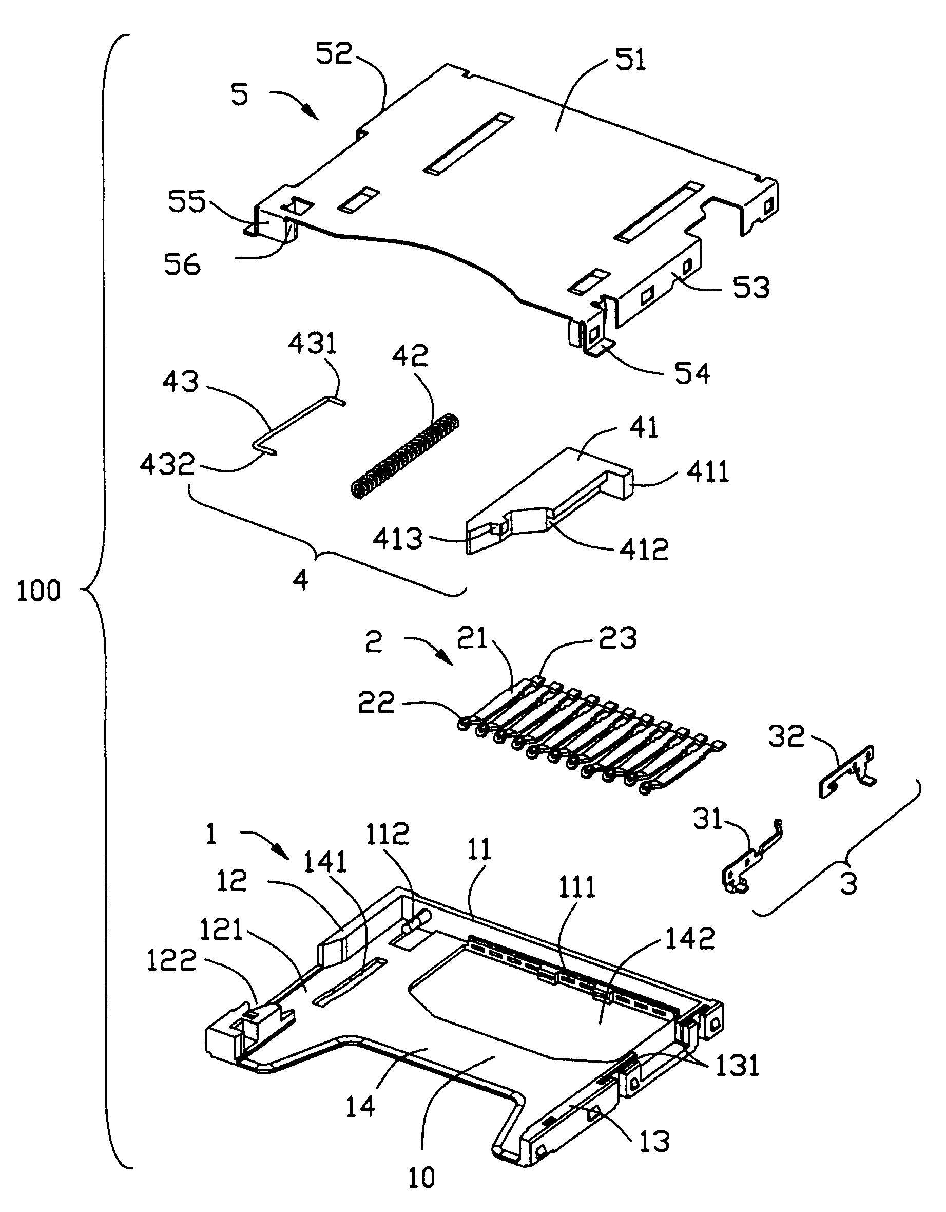
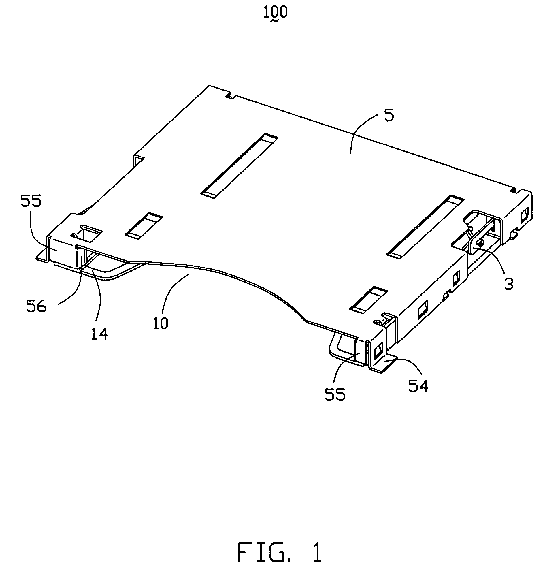
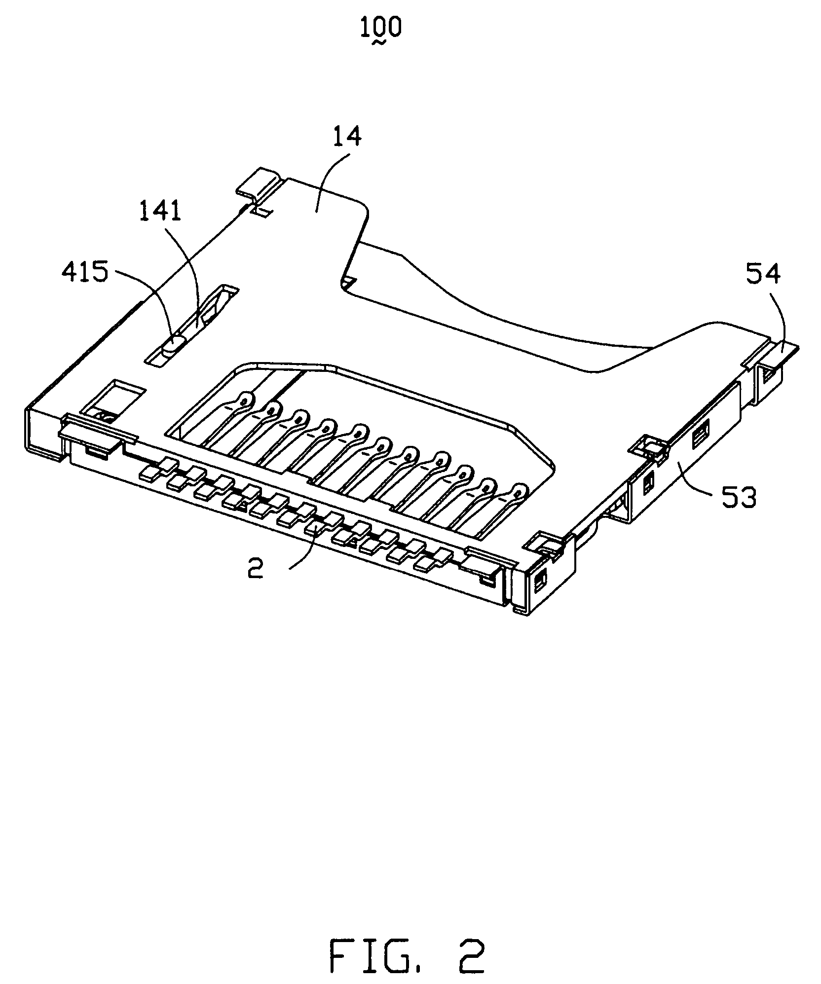
[0020]Referring to FIGS. 1–6, a card connector 100 for connecting a card 60 (shown in FIG. 6) to a circuit board (not shown) in accordance with the preferred embodiment of the present invention comprises an insulative housing 1, a plurality of contact terminals 2 received in a rear portion of the housing 1, a switch terminal 3 received in one side of the housing 1, an ejector 4 received in the other side of the housing 1, a shielding member 5 covering on top of the housing 1.

[0021]The housing 1 has a rear wall 11, a first side wall 12, a second side wall 13 and a bottom wall 14, all of which define an upward opening 10 together. The rear wall 11 has a plurality of contact terminal receiving slots 111 for receiving the plurality of contact terminals 2. A post 112 is formed on the rear wall 11 adjacent to the first side wall 12 and extends forwardly into the ...


PUM


Abstract

An electrical card connector (100) includes a housing (1) having a rear wall (11), and first and second side walls (12 and 13) substantially parallel extending forwards form the rear wall; a shielding member (5) covering on the housing and defining a receiving cavity together with the first and second side walls for receiving an electrical card (6), the receiving cavity having a font entry from which the electrical card is inserted into the receiving cavity; and a number of terminals (2) disposed in the housing and each having a contact portion (22) extending into the receiving cavity for contacting the electrical card. The shielding member is provided with a pair of guiding plates (56) at the front entry of the receiving cavity and disposed between the first and second side walls for guiding the electrical card into the receiving cavity.

Description

BACKGROUND OF THE INVENTION[0001]1. Field of the Invention[0002]The present invention relates to an electrical card connector, specifically to a card connector provided for electrically connecting a card to a circuit board.[0003]2. Description of Related Art[0004]In electronic appliances, such as portable telephones, PDA, cameras and the like, various expandable functions are achieved by installing IC cards, such as SIM (subscriber identify module) card, MMC (multimedia card), SD (secure digital) card, MS (memory stick) card and the like therein. Such an IC card is usually connected to the circuit board via a card connector.[0005]FIG. 9 of the attached drawings shows a conventional card connector (shown as U.S. Pat. No. 6,685,490) including an insulative housing 3, a plurality of first terminals 5 and second terminals 6 retained in the insulative housing 3, a shielding member 2 covering on top of the insulative housing 3, and an ejector 4 positioned on one side of the insulative hou...

Claims


Application Information

Patent Timeline
Patent Type & Authority Patents(United States)
IPC IPC(8): H01R24/00
CPCH01R23/6873H01R13/629H01R13/703H01R13/6593H01R13/6595
Inventor CHEN, KUN-HUACHUNG, YUNG-CHIEN
Owner HON HAI PRECISION IND CO LTD
Why Eureka
Try Eureka