
Aerodynamic drag reducing system with retrofittable, selectively removable frame

a drag reduction system and frame technology, applied in the field of aerodynamic drag reduction systems, can solve the problems of system problems affecting the function of the vehicle, complex and time-consuming process, and have not been met with much commercial or practical success, and achieve the effect of quick and easy operation

Inactive Publication Date: 2007-04-24
COSGROVE WILLIAM E +1
View PDF47 Cites 134 Cited by
  • Summary
  • Abstract
  • Description
  • Claims
  • Application Information

AI Technical Summary

Benefits of technology

"The present invention is an aerodynamic drag reducing system for land vehicles. It consists of a selectively removable frame, a securement assembly, a drag reduction member, and a connecting assembly. The securement assembly attaches the frame to the vehicle, while the connecting assembly attaches the drag reduction member to the frame. The system can be easily and quickly installed by one person, and it does not require any permanent modifications to the vehicle. Additionally, the system can be easily removed and collapsed for compact storage. The technical effects of this invention include reducing aerodynamic drag, improving fuel efficiency, and providing a simple and easy-to-use installation process."

Problems solved by technology

Aerodynamic drag reducing systems known in the art have been not been met with much commercial or practical success.
Significant drawbacks of aerodynamic drag reducing systems known in the art include: (i) the complicated and time consuming process of securing the system to the vehicle; (ii) the need to permanently modify the vehicle to which the system is secured; and (iii) the problems the system can pose for the functions of the vehicle, such as loading and unloading a semi-tractor trailer to which the system is secured.
Often, the person or entity who owns the semi-tractor trailer is not concerned about the gas efficiency of the tractor pulling the trailer, and would not realize a benefit from use of a drag reduction system.
As such, the owner of the trailer may protest to any permanent modification to his or her trailer.

Method used


Image

  • Aerodynamic drag reducing system with retrofittable, selectively removable frame
  • Aerodynamic drag reducing system with retrofittable, selectively removable frame
  • Aerodynamic drag reducing system with retrofittable, selectively removable frame

Examples


Embodiment Construction

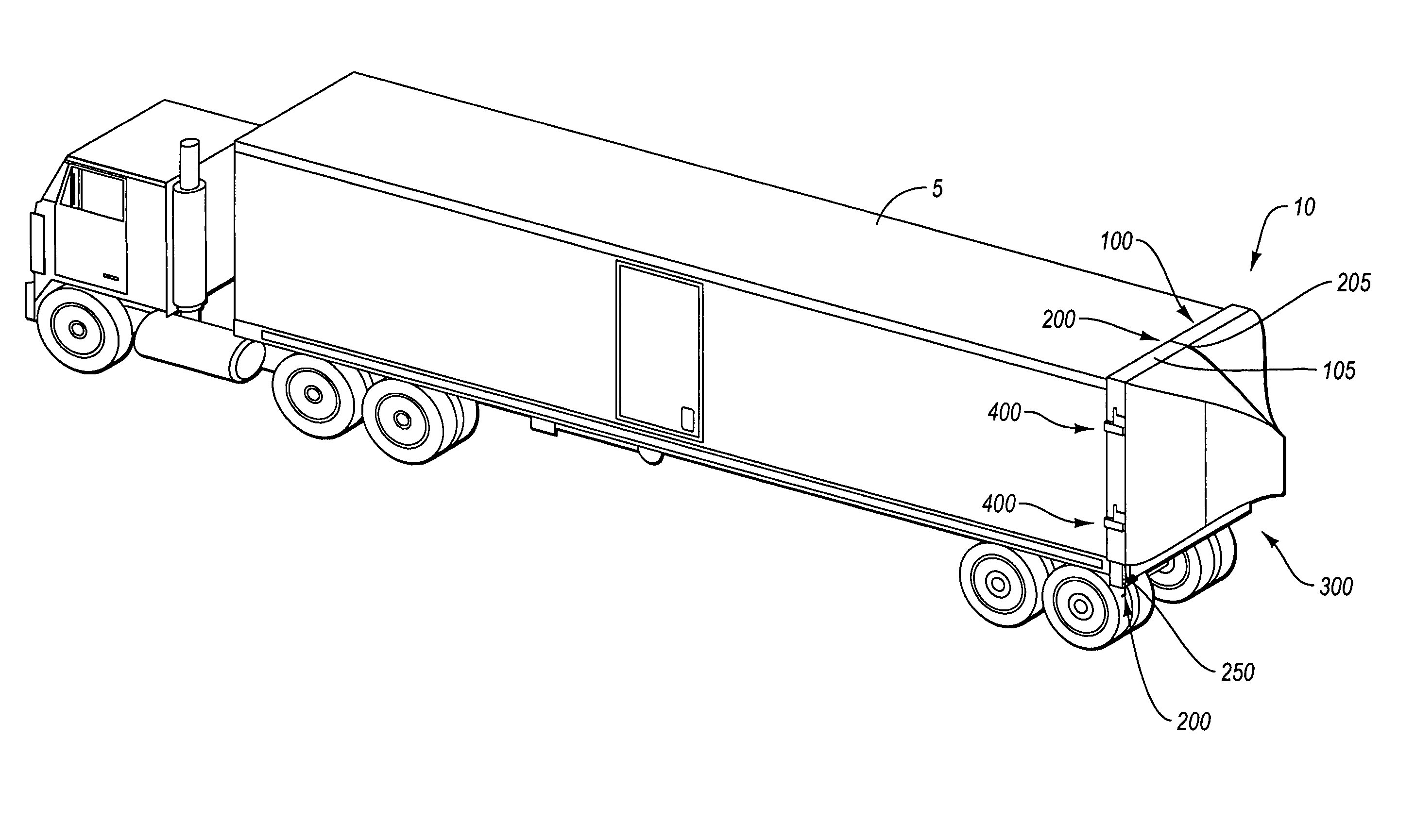
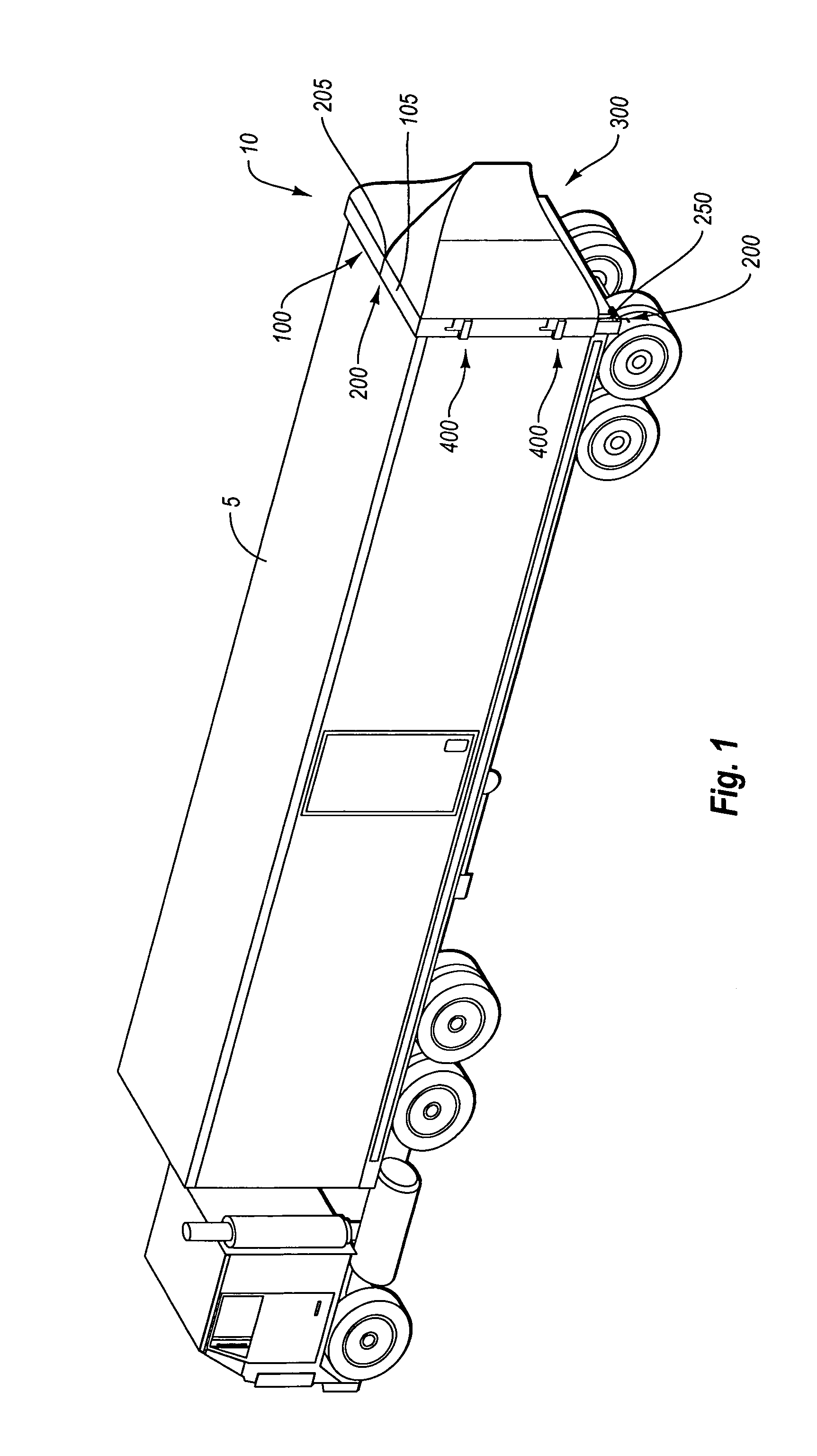
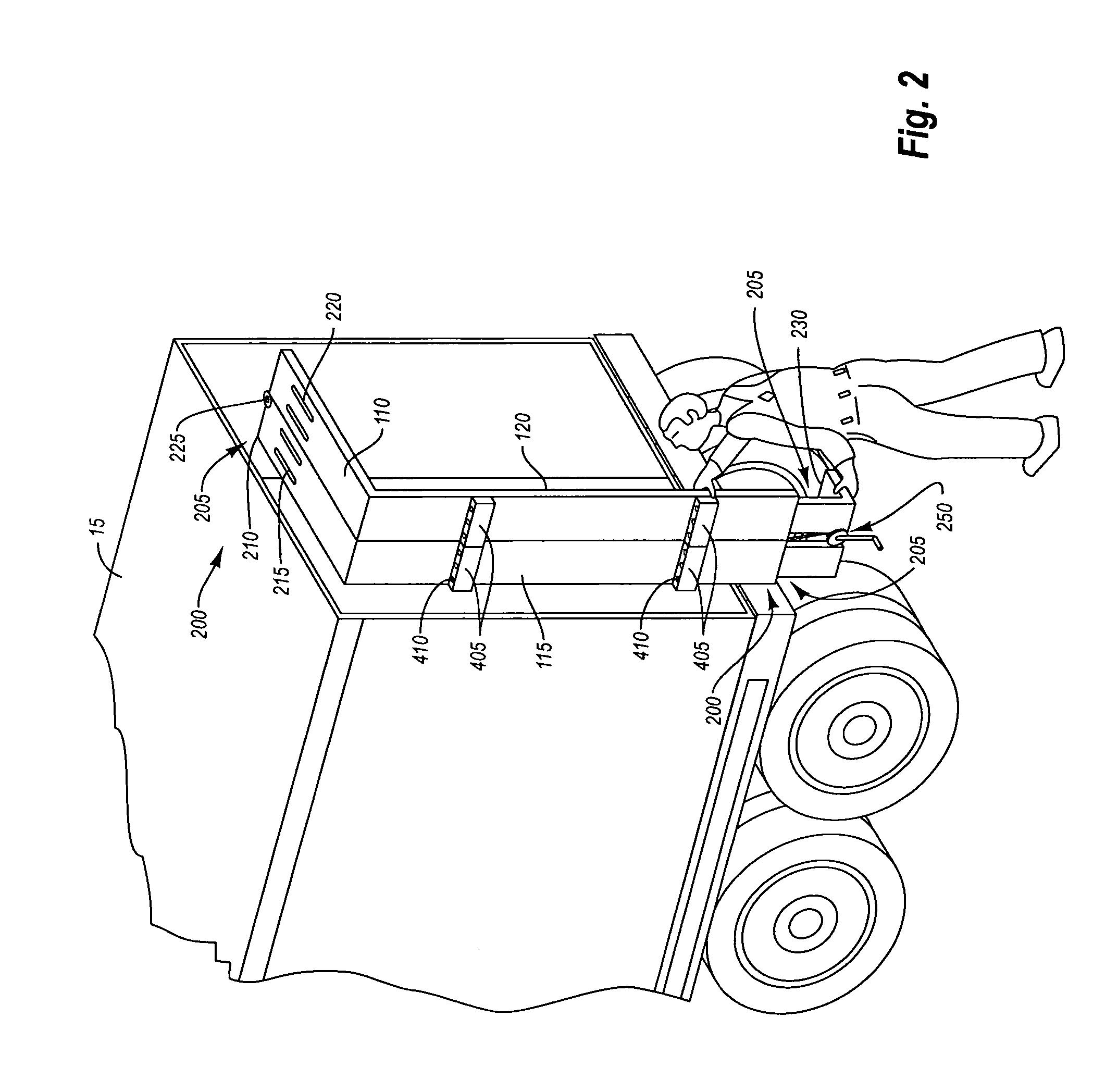
[0028]The present invention relates to a drag reduction system which can quickly and easily be retrofitted to operate with a land vehicle. The drag reduction system is designed to reduce the aerodynamic drag created by land vehicles, thus increasing vehicle efficiency, and thereby reducing fuel costs. Unlike other drag reduction systems, this invention can be easily and quickly secured to a land vehicle by one person. Additionally, the drag reduction system of the present invention can be secured to a vehicle without permanently modifying the vehicle, thereby making the drag reduction system retrofittable. Finally, the aerodynamic drag reduction system, when not in use, can be selectively collapsed, such that the entire system can be effectively stored in a confined space.

[0029]FIG. 1 illustrates an exemplary embodiment of an aerodynamic drag reducing system 10 as it may be used to reduce drag on a land vehicle 5. In the illustrated embodiment, drag reducing system 10 includes a sel...


PUM


Abstract

The present invention relates to an aerodynamic drag reducing system for land vehicles, in particular semi-tractor trailers. The drag reducing system includes a selectively removable frame and a drag reduction member. The selectively removable frame can adapt to conform to at least one of the width or height of the land vehicle, and can be secured thereto by a securement assembly. In one embodiment, the drag reducing system can be folded and collapsed for compact storage. The drag reducing system can be easily and quickly secured to the back end of a semi-tractor trailer without tools and without requiring that any permanent modifications be made to the trailer. In one embodiment, drag reducing system includes a hinge joint assembly to facilitate installation, removal, and repositioning of drag reducing system.

Description

BACKGROUND OF THE INVENTION[0001]1. The Field of the Invention[0002]The present invention relates to an aerodynamic drag reduction system for use on trucks and trailers. More specifically, the invention relates to a drag reducing, aerodynamic fairing that can be quickly and temporarily attached to the rear of a trailer to reduce aerodynamic drag.[0003]2. Background and Relevant Technology[0004]The design of a moving vehicle has always been viewed, at least in part, as both cosmetic and utilitarian. Cosmetic-based design features are based primarily on enhancing the appeal of a vehicle to the consuming public. Utilitarian-based features, on the other hand, are based on what the vehicle must have to be effective for its intended purpose. For example, the engine and vehicle size are determined, in part, by how many passengers the vehicle should carry, or what size load must be transported.[0005]In recent years, utilitarian and cosmetic concerns have merged to increase focus on preservi...

Claims


Application Information

Patent Timeline
Patent Type & Authority Patents(United States)
IPC IPC(8): B60J1/00
CPCB62D35/001
Inventor COSGROVE, WILLIAM E.COSGROVE, TIMOTHY C.
Owner COSGROVE WILLIAM E
Learn More