
Empty container detection using container side pressure sensing

a technology of container side pressure and detection container, which is applied in the direction of digital computer details, process and machine control, instruments, etc., can solve the problems of difficult monitoring and determining when the fluid container becomes empty, air entering, and method is prone to errors

Active Publication Date: 2007-04-17
CAREFUSION 303 INC
View PDF47 Cites 83 Cited by
  • Summary
  • Abstract
  • Description
  • Claims
  • Application Information

AI Technical Summary

Benefits of technology

This method provides a reliable and cost-effective means to detect empty containers, preventing air entry and ensuring accurate fluid delivery by providing timely alerts and adjusting infusion rates, thus enhancing patient safety and reducing caregiver monitoring burdens.

Problems solved by technology

One problem that exists with all infusions is that it is difficult to monitor and determine when the fluid container becomes empty, necessitating a change of container or other attention from a care-giver.
If the empty or nearly empty container is not replaced or replenished, air may enter the infusion line, which is generally considered to be an undesirable condition.
This method is prone to errors due to mistakes or inaccurate estimations of the fluid infusion rate or the amount of fluid remaining in the container.
However, frequent errors due to incorrect estimation of container volume or inaccurate setting of the secondary volume-to-be-infused renders this method unreliable, requiring frequent monitoring by care-givers to ensure that the proper fluid is being infused at the proper rate, and to prevent air from entering into the infusion line in the instance of a fault such as a non-flowing checkvalve.
In many cases, the various therapeutic fluids are not compatible with each other, and so care must be taken to avoid mixing the fluids in the manifold.
While current pumps can be programmed to deliver the exemplary therapeutic regimen described above, as with the other examples, errors in setting the pumps for the volumes to be infused, or the occurrence of an empty container, can complicate the delivery of the infusion fluids and require frequent monitoring during the infusion.
However, noise sources such as patient or equipment movement, cross coupling between fluid lines or pumping channels made this approach difficult to carry out in practice.

Method used


Image

  • Empty container detection using container side pressure sensing
  • Empty container detection using container side pressure sensing
  • Empty container detection using container side pressure sensing

Examples


Embodiment Construction

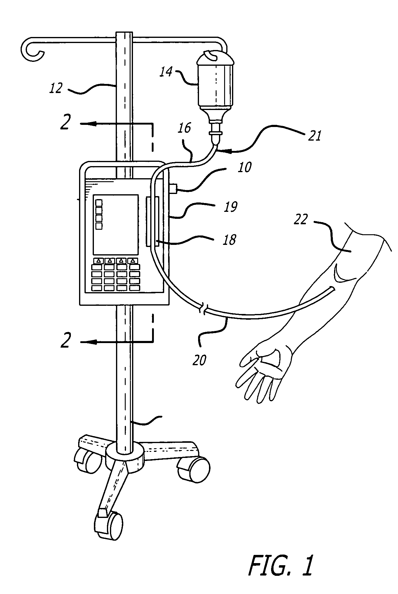
[0025]Referring now to FIG. 1, there is shown an infusion pump set-up, generally designated 10, shown in use in its intended environment. In particular, the infusion pump set-up 10 is shown mounted to an intravenous (I.V.) pole 12 on which a fluid source 14 containing an I.V. fluid is held. The fluid source 14 is connected in fluid communication with an upstream fluid line 16. The upstream fluid line 16 is a conventional I.V. infusion-type tube typically used in a hospital or medical environment, and is made of any type of flexible tubing appropriate for use to infuse therapeutic fluids into a patient, such as polyvinylchloride (PVC). The upstream fluid line 16 is connected with another tube portion 18 that is flexible and is mounted in operative engagement with a peristaltic pumping apparatus 19, for propelling fluid through a downstream fluid line 20, for example, to a patient's arm 22. It will be understood by those skilled in the art that the upstream fluid line 16, the flexible...


PUM


Abstract

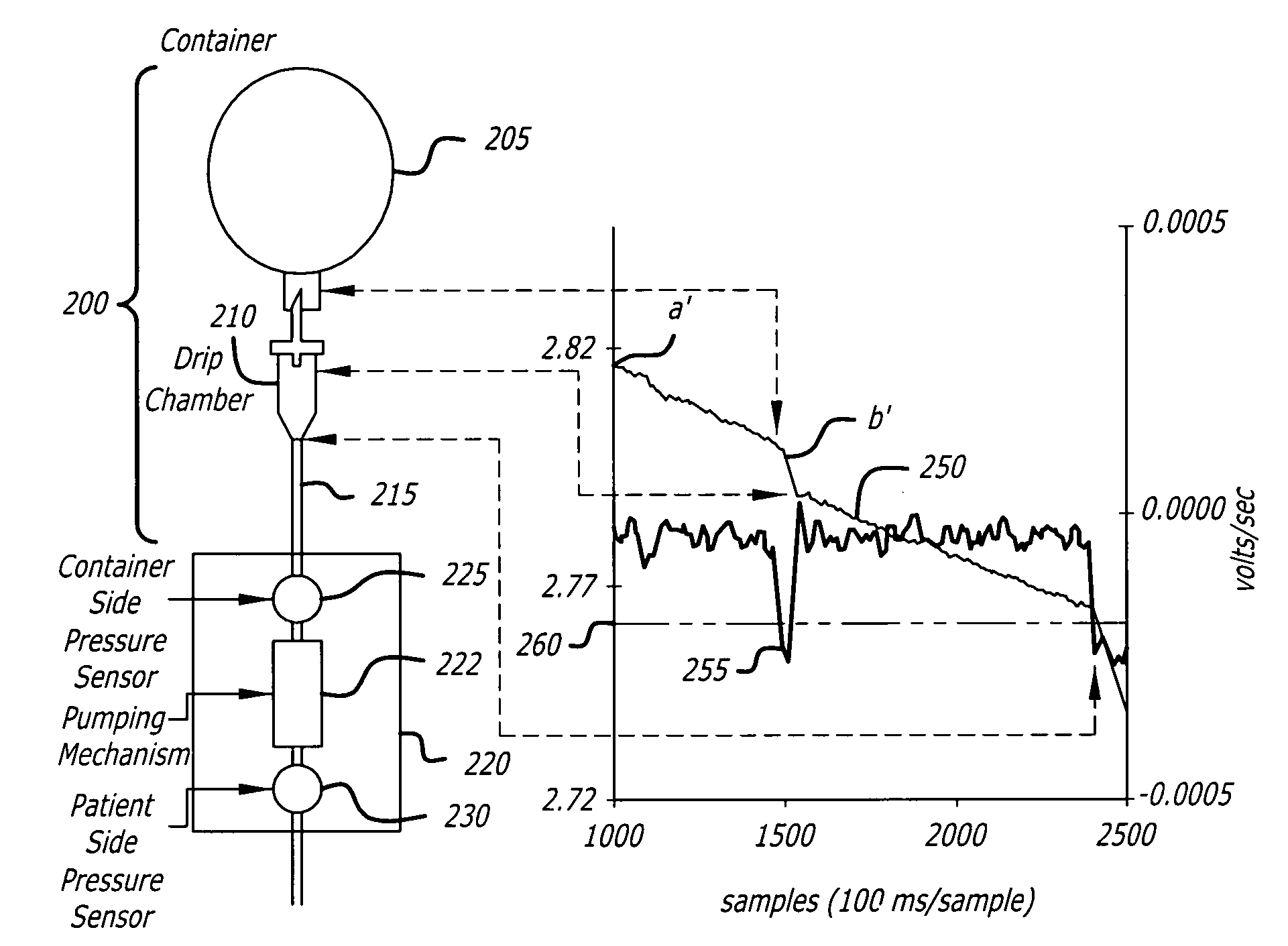
A system and method for monitoring changes in the pressure of a fluid line upstream of an infusion pump to determine when a fluid container has emptied, and to provide a signal indicating that the container needs replacement or replenishment. The difference between averaged pressures over separate time periods is monitored to determine when the fluid container is empty. The system and method are applicable to primary and secondary fluid container setups and can detect the point where the secondary has been emptied and the primary flow has resumed.

Description

BACKGROUND OF THE INVENTION [0001]1. Field of the Invention[0002]The present invention generally relates to a system and method for determining when an infusion fluid container has emptied, or is about to empty, as a result of fluid being withdrawn from the container. More specifically, the present invention relates to a system including an infusion pump having a sensor that is capable of monitoring and detecting pressure within the container-side of a fluid “infusion set” so as to determine when the associated fluid container is empty, or about to become empty. Upon such detection, the system may provide a local or remote audible and / or visual alert to a caregiver administering or monitoring the infusion and may initiate pre-programmed changes to the flow of fluid including changing to an alternate flow rate or stopping infusion.[0003]2. General Background and State of the Art[0004]Infusion of therapeutic fluids to treat or nourish patients is commonly used in hospitals and other m...

Claims


Application Information

Patent Timeline
Patent Type & Authority Patents(United States)
IPC IPC(8): G06F15/00A61M5/142A61M5/168
CPCA61M5/1684A61M5/16854A61M5/14228A61M2205/18A61M2205/3561
Inventor VANDERVEEN, TIMOTHY W.BUTTERFIELD, ROBERT D.
Owner CAREFUSION 303 INC
Learn More