Hydraulic or pneumatic machine with tilting blades
a technology of hydraulic or pneumatic machines and blades, which is applied in the direction of propellers, water-acting propulsive elements, rotary piston engines, etc., can solve the problems of high stress on the rotor bearings and the outlet couple with variable value, high labor intensity, and high labor intensity. , to achieve the effect of low stress, low pressure loss value and small overall dimensions
- Summary
- Abstract
- Description
- Claims
- Application Information
AI Technical Summary
Benefits of technology
Problems solved by technology
Method used
Image
Examples
example 1
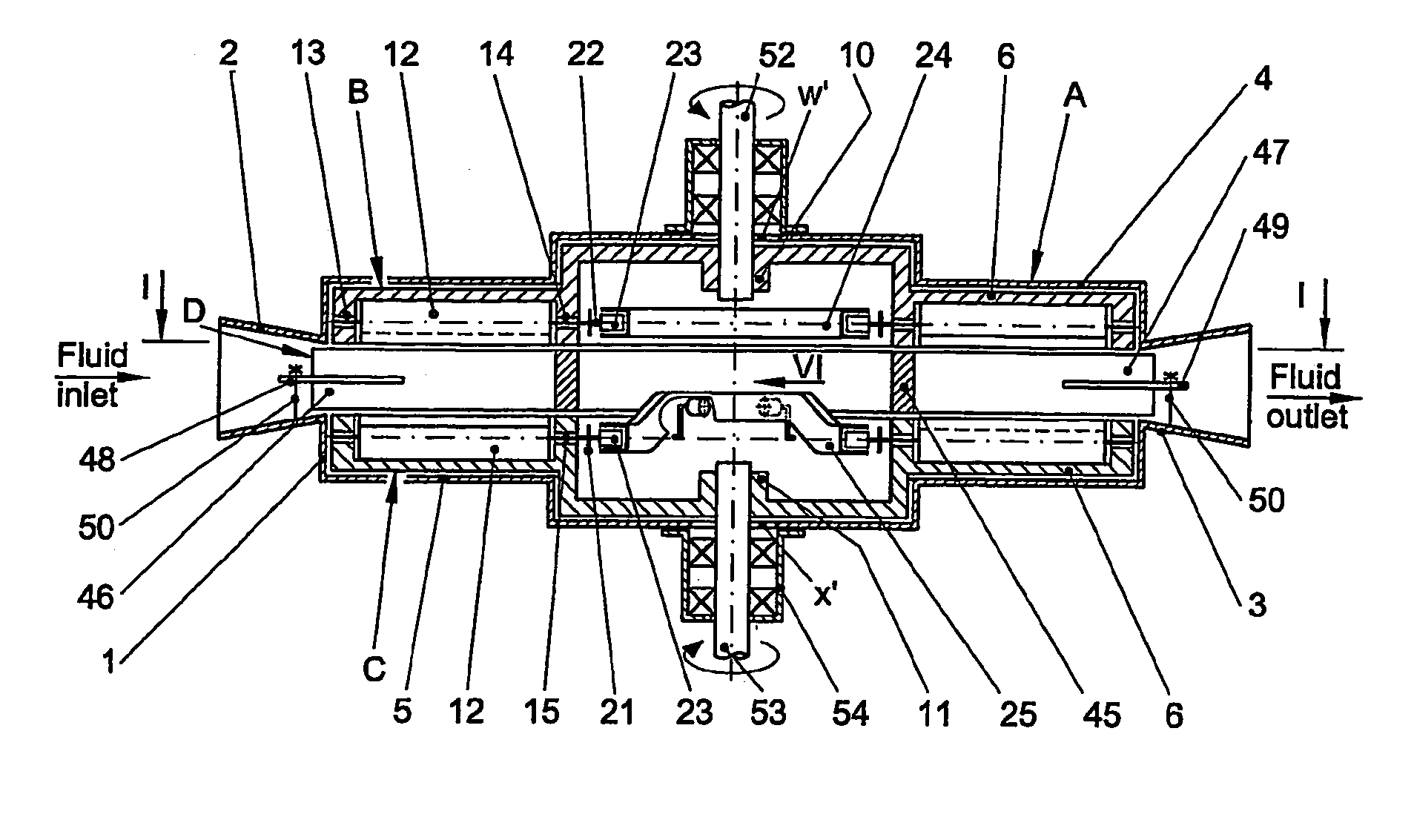
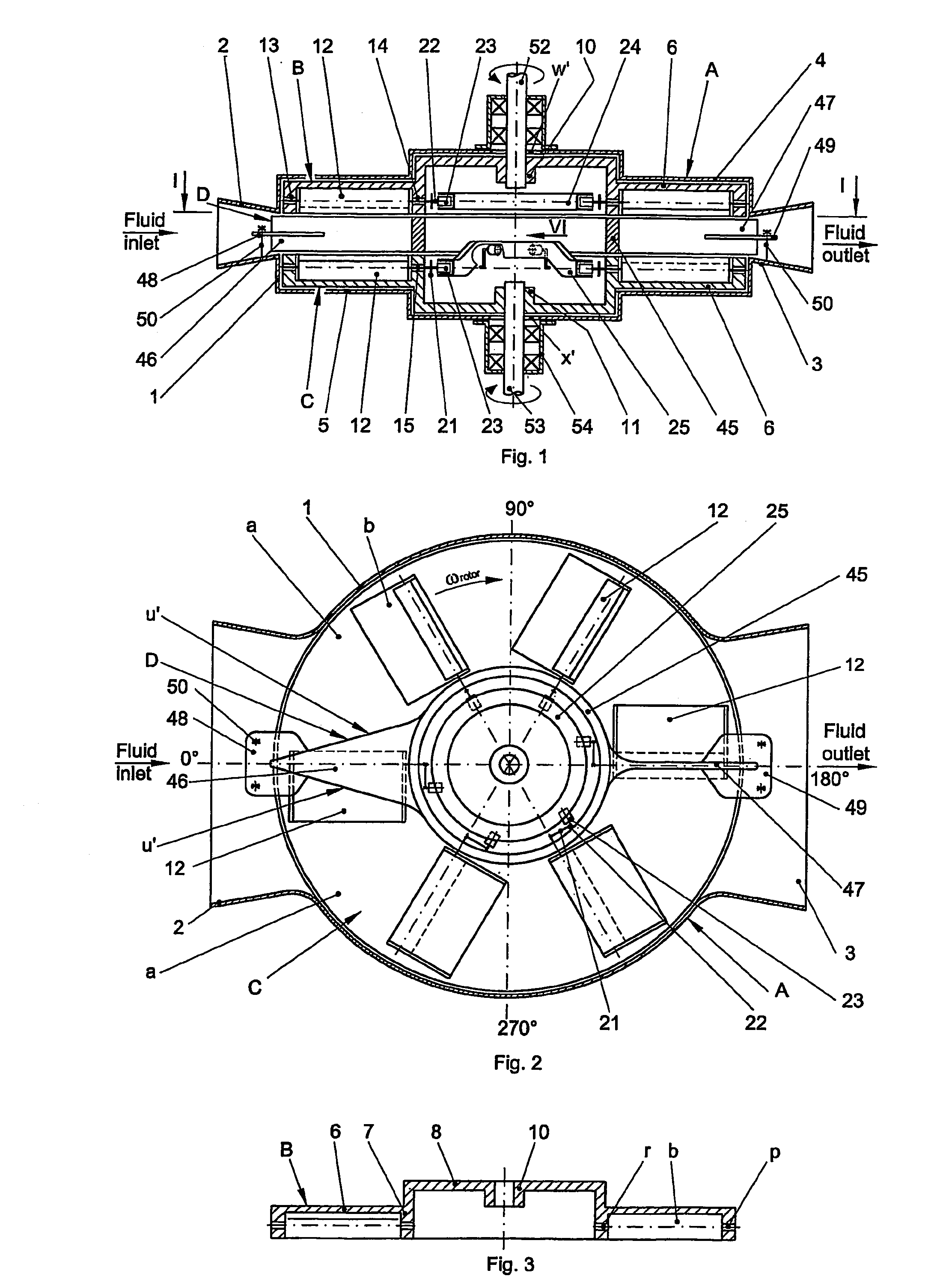
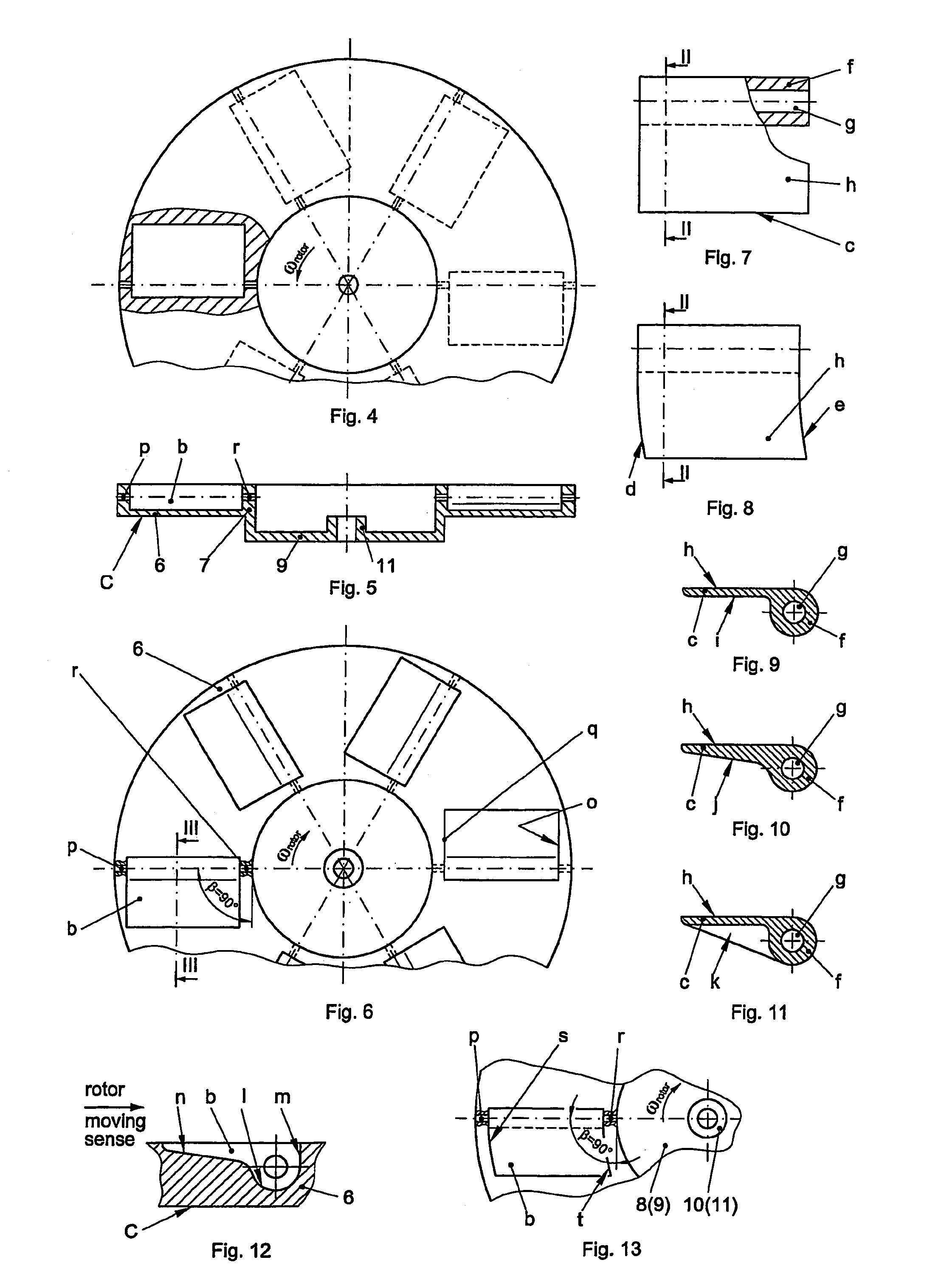
[0104]The hydraulic or pneumatic machine with vertical shaft made according to the invention consists of a fixed stator A, two disk like rotors, an upper one B and a lower one C, spaced from one another by a drum D connected onto stator A, all elements being in line, the parallel front faces of the two rotors being equipped with tilting blades which, due to some driving mechanisms of their own, can take against the rotor either a passive position—the blade in the front plane of the rotor, or an active position—the blade inclined by an α≦90° angle against the front face of said rotor. Inside the machine, two symmetrical, semicircular channels a are formed and due to the manner the driving mechanisms are arranged within the machine, the blades of one rotor are in active position, obstructing the passage of respective channel while the blades of the other rotor are in passive position, so that the circulating fluid along the two channels a flowing to the same sense, actuates the blades...
example 2
[0160]The hydraulic or pneumatic machine with vertical shaft, with multistage channels, made according to the invention, allows the circulation of a larger fluid flow, as compared to the one in the preceding example, by increasing the fluid passage section due to the use of several rotors of same diameter, namely: two extreme rotors with one front face each, provided with tilting blades 12, of which one, either the upper rotor B or the lower rotor C is mounted on one of the machine shafts and the other, a ring rotor E without supporting elements on machine shaft, and a number of disk F or ring G intermediate rotors with two front faces each, provided with tilting blades 12 on both faces, the blades on one face being mirror like arranged to those on the other face, their size and number being the same for the front faces of the rotors on each stage while they can vary from one stage to the other.
[0161]The tilting blades 12 of each rotor are arranged in such a manner as the neighbouri...
example 3
[0194]The hydraulic or pneumatic machine with tilting blades, according to the invention, for working fluids under static pressure.
[0195]In view of adjusting the machine to run as a hydraulic or pneumatic motor using a working fluid under static pressure, in the circular space between the cylindrical shell 1 of stator A and the cylindrical body 45 of drum D, interdependent to it, is fixed a cylindrical ring 92 with the height corresponding to the distance between the front surfaces of rotors B, C, having on each front face of it a channel a″ of variable depth, for the action of the tilting blades 12 of the rotor close to said surface, the two channels connecting the fluid inlet and outlet nozzle, diametrically opposed, each having an initial zone b″, with a depth increasing to the rotation sense of said rotor, on the angular sector γ1 specific to blade transition from passive to active position, a middle zone c″ open to the other rotor, with constant depth, equal to the height of th...
PUM
 Abstract
Description
Claims
Application Information
 - R&D
- Intellectual Property
- Life Sciences
- Materials
- Tech Scout
- Unparalleled Data Quality
- Higher Quality Content
- 60% Fewer Hallucinations
Browse by: Latest US Patents, China's latest patents, Technical Efficacy Thesaurus, Application Domain, Technology Topic, Popular Technical Reports.
© 2025 PatSnap. All rights reserved.Legal|Privacy policy|Modern Slavery Act Transparency Statement|Sitemap|About US| Contact US: help@patsnap.com


