
Ultrasonic ranging system and method thereof in air by using parametric array

a parametric array and ultrasonic wave technology, applied in the field of ultrasonic ranging system and method thereof, can solve the problems of increasing the frequency of ultrasonic wave, reducing the measurable range of a distance, and difficulty in mechanically implementing the larger radius of the piston-shaped ultrasonic wave generator

Active Publication Date: 2007-03-27
MOON WONKYU
View PDF4 Cites 12 Cited by
  • Summary
  • Abstract
  • Description
  • Claims
  • Application Information

AI Technical Summary

Benefits of technology

"The present invention provides an ultrasonic ranging system and method for measuring a distance to an object in air using a pulse of difference frequency wave created during a propagation in an air after transmitting an ultrasonic pulse generated by a parametric array. The system includes a controller, pulse generators, modulator, amplifiers, ultrasonic wave actuator, ultrasonic wave sensor, band pass filter, and ranging processor. The technical effects of the invention include improved accuracy and efficiency in measuring air-to-object distances, as well as simplified and automated operation."

Problems solved by technology

However, the method of increasing the frequency of the ultrasonic wave has a drawback that a measurable range of a distance decreases, because the ultrasonic wave is attenuated in proportional to square of the frequency.
However, it is practically difficult to implement the larger radius of the piston-shaped ultrasonic wave generator mechanically.
As described above, the conventional ultrasonic distance measuring method has a limitation in reducing the beam width of the ultrasonic wave pulse, in that a pulse having the high frequency is directly transmitted, reflected and detected for the ranging.
Consequently, the conventional method has the drawback of poor resolution in the spatial domain.
Still another drawback of the conventional ultrasonic distance method is that a side lobe is formed in a direction other than the central direction of the propagation, while a main component of the ultrasonic pulse is propagating into the central direction thereof.
Consequently, the side lobe causes a cross talk, thereby making it difficult to measure the distance to the target object precisely.

Method used


Image

  • Ultrasonic ranging system and method thereof in air by using parametric array
  • Ultrasonic ranging system and method thereof in air by using parametric array
  • Ultrasonic ranging system and method thereof in air by using parametric array

Examples


Embodiment Construction

[0021]Hereinafter, a preferred embodiment of an ultrasonic ranging system and method thereof for measuring the distance to the object by using a parametric array in accordance with the present invention will be described in detail with reference to the accompanying drawings. In the specification and the accompanying drawings, like reference numerals will be given to like parts having substantially same functions and redundant description thereof will be omitted.

[0022]A technology of generating a difference frequency wave by using a parametric array has been applied to an underwater low frequency active SONAR (Sound Navigation Ranging) system used. According to “Nonlinear underwater acoustics”, (The American Institute of Physics, New York, 1987) authored by B. K. Novikov, O. V. Rudenko, and V. I. Timoshenko, the technology using parametric array has been widely adopted due to advantages that a low frequency wave corresponding to the difference frequency wave, which has a high directi...


PUM


Abstract

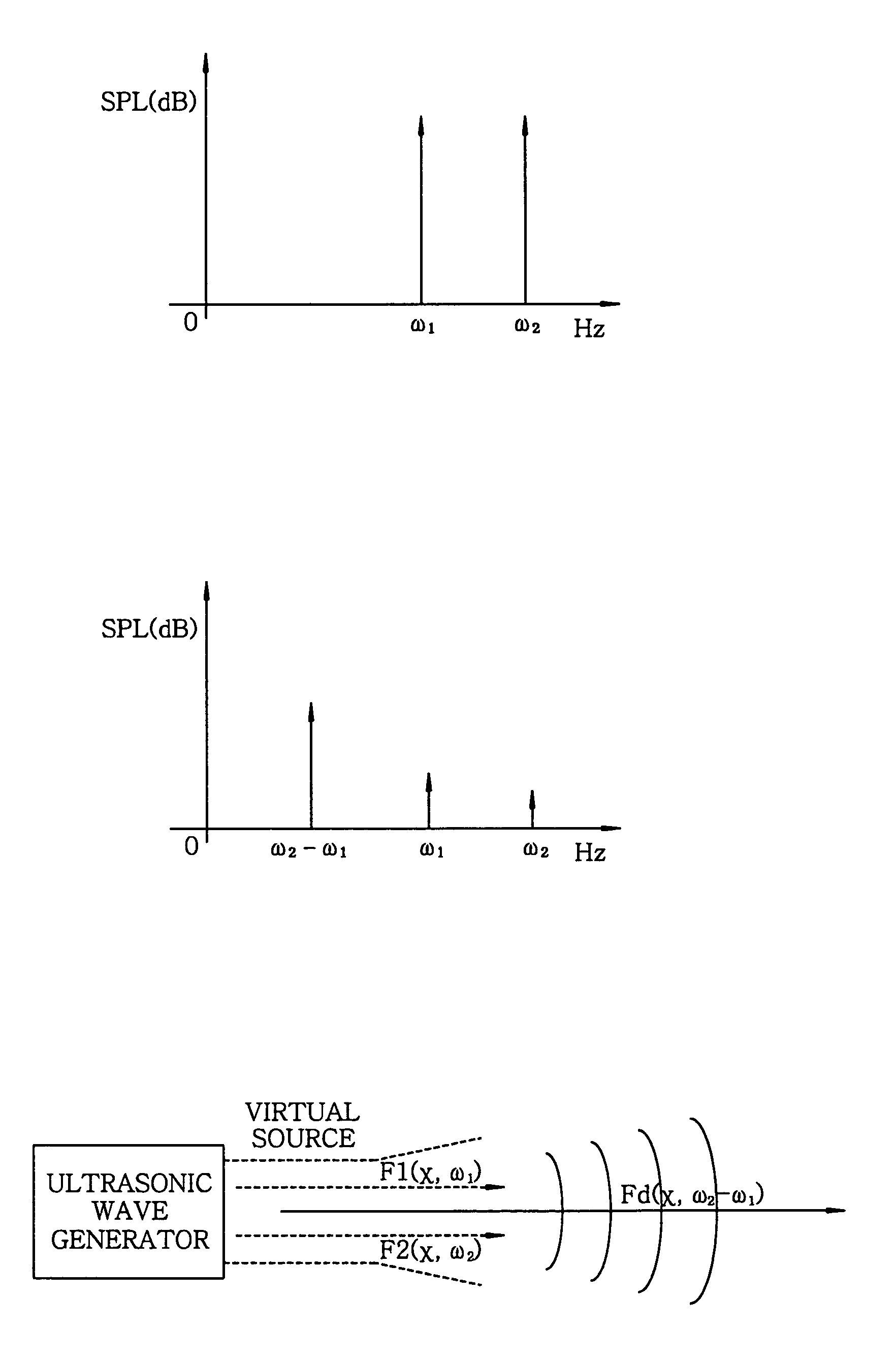
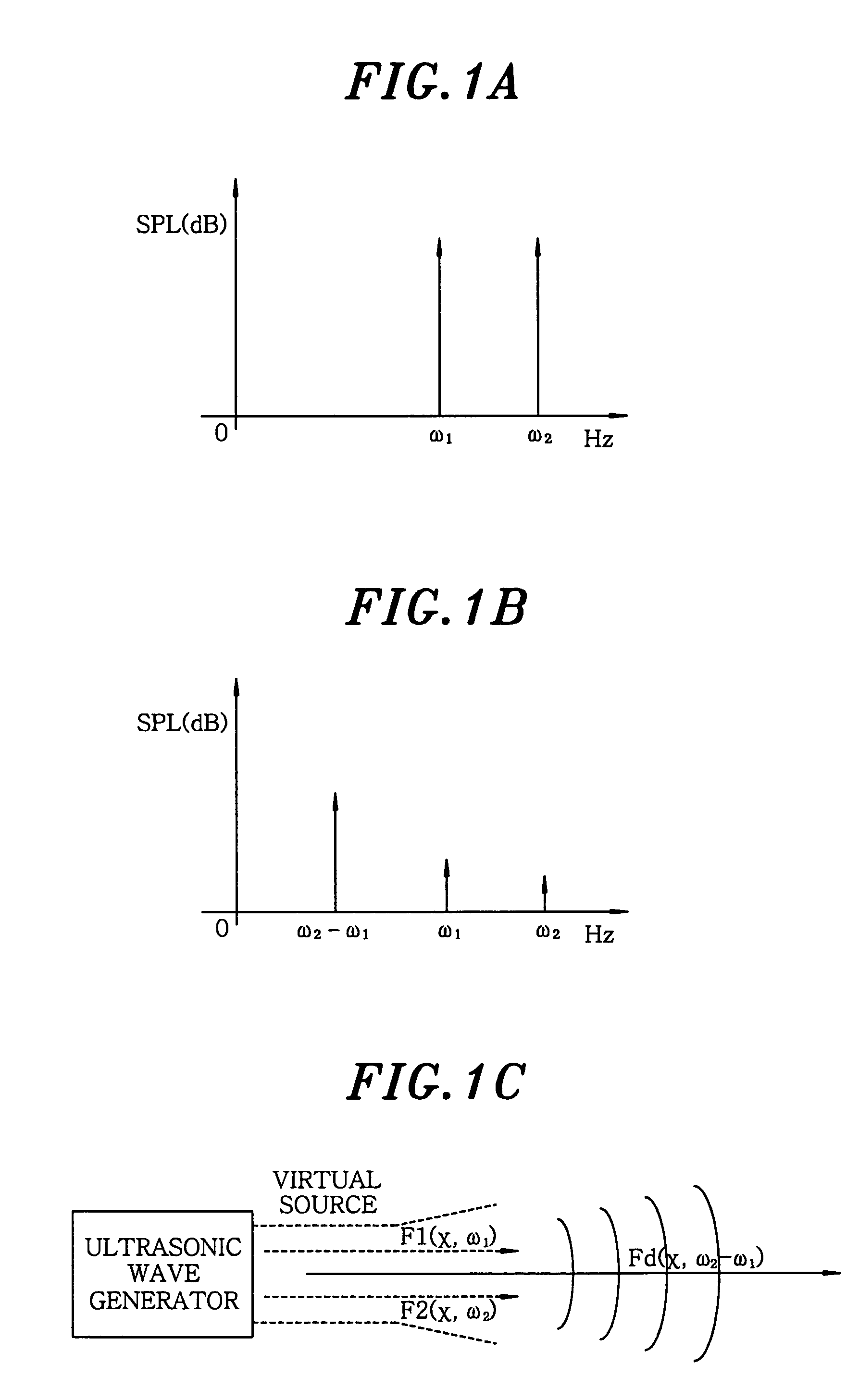
An ultrasonic ranging method for measuring a distance to an object in an air includes the steps of generating a first and a second primary ultrasonic waves having a frequency f1 and f2, respectively, transmitting the first and the second primary ultrasonic waves in a same direction, wherein a secondary ultrasonic wave having a frequency corresponding to the difference of two frequencies fd=f1−f2 is created by a nonlinear property of the air and radiated to the object, detecting an echo pulse of the secondary ultrasonic wave reflected from the object, and measuring the distance to the object based on a propagation time of the secondary wave.

Description

FIELD OF THE INVENTION[0001]The present invention relates to an ultrasonic ranging system and method thereof; and, more particularly, an ultrasonic ranging system and method for measuring a distance to an object based on a propagation time of an ultrasonic pulse by generating the ultrasonic pulse toward an object in an air and detecting an echo pulse reflected therefrom.BACKGROUND OF THE INVENTION[0002]Currently, there are introduced several methods for measuring a distance to an object by using an ultrasonic wave in an air. Representative examples of the distance measuring method employing the ultrasonic wave are, for example, a pulse echo method, a phase angle method, a frequency modulation method and a correlation method. Among those methods, the pulse echo method is the most simple and has been adopted for long period of time in many areas such as a ranging sensor in a mobile robot and an intelligent traffic system.[0003]Herein, therefore, there will be described a method which ...

Claims


Application Information

Patent Timeline
Patent Type & Authority Patents(United States)
IPC IPC(8): G01S15/00G01S5/18G01S7/524G01S15/10
CPCG01S15/102G01S7/523G01S15/101G01S15/14
Inventor MOON, WONKYULEE, HAKSUE
Owner MOON WONKYU
Learn More