Firing mechanism for semi-automatic pistols

a semi-automatic pistol and firing mechanism technology, applied in the direction of firing/trigger mechanism, shoulder-fired small arms, weapons, etc., can solve the problems of high manufacturing cost, complex manufacturing, and large number of parts

Inactive Publication Date: 2007-03-27
SMITH & WESSON
View PDF2 Cites 44 Cited by
  • Summary
  • Abstract
  • Description
  • Claims
  • Application Information

AI Technical Summary

Problems solved by technology

The principal drawback of this type of mechanism is that it includes numerous parts and is relatively complex and expensive to manufacture.

Method used


Image

  • Firing mechanism for semi-automatic pistols
  • Firing mechanism for semi-automatic pistols
  • Firing mechanism for semi-automatic pistols

Examples


Embodiment Construction

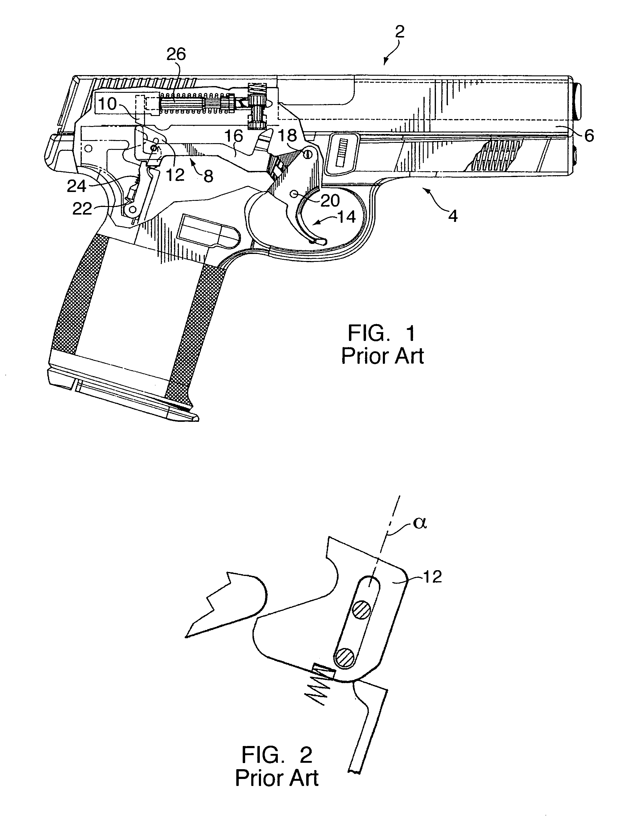
[0018]Referring to FIG. 1, a prior art semiautomatic pistol or handgun 2 is shown and generally comprises a high impact polymeric frame 4, slide 6 and a firing mechanism 8. The prior art firing mechanism is a striker-type firing pin mechanism and is depicted in U.S. Pat. No. 5,386,659, which is hereby incorporated by reference in its entirety. The striker or firing pin 26 includes a depending leg 10, which selectively engages a sear 12 of the firing mechanism.

[0019]The prior art firing mechanism 8 further includes a trigger 14 that pivots to move a trigger bar 16 longitudinally in response to operation of the trigger. The trigger may be of unitary construction, as shown, or of a two-piece articulated construction as depicted in U.S. Pat. No. D371591, which is hereby incorporated by reference in its entirety. In either case, when one actuates the trigger, it will move rearward about the pivot pin 18 and its pivotable movement will be transmitted to the trigger bar by a pin 20 (FIG. 2...


PUM


Abstract

A firing mechanism for a firing pin striker operated semiautomatic handgun that includes a sear, a sear block housing, and a pivot arm. The sear is attached to the pivot arm and includes two angled surfaces and an edge portion for controlling the firing pin. The edge portion abuttingly engages an extension of the firing pin adapted to be in planar movement with the edge portion of the sear. The pivot arm and sear move together in an arcuate path about the pin in response to trigger firing movement. Unlike prior art firing mechanisms, the sear does not move vertically along an axis perpendicular to the bore of the handgun. The arcuate movement of the pivot arm causes the edge portion of the sear to disengage from the firing pin. The angled surfaces of the sear allow the firing pin extension to pass over the sear discharging the firearm.

Description

CROSS REFERENCE TO RELATED APPLICATIONS[0001]This application claims the benefit of U.S. Provisional Patent Application Ser. No. 60 / 446,123 filed on Feb. 10, 2003, entitled “AN IMPROVED FIRING MECHANISM FOR SEMI-AUTOMATIC PISTOLS,” herein incorporated by reference in its entirety.FIELD OF THE INVENTION[0002]The present invention relates generally to a firing mechanism for a semiautomatic pistol or handgun which employs a firing pin striker mechanism and more particularly to a firing mechanism with a simplified sear block assembly.BACKGROUND OF THE INVENTION[0003]One type of firing mechanism commonly used in semiautomatic handguns includes a hammer which is pivotable from a rearward cocked position to a forward position for impacting the firing pin. A sear releasably retains the hammer in its cocked position with the hammer spring or main spring in compression. When the trigger is actuated, the sear is moved to release the hammer that is moved by the stored energy of the main spring,...

Claims


Application Information

Patent Timeline
Patent Type & Authority Patents(United States)
IPC IPC(8): F41A3/00
CPCF41A19/12F41A19/32F41A19/31
Inventor CURRY, BRETT
Owner SMITH & WESSON
Why Eureka
Try Eureka