Laser marking device for serial I-joist cutouts
a marking device and serial technology, applied in the direction of mechanical measuring arrangement, instruments, manufacturing tools, etc., can solve the problems of difficult marking of all individual reference points, a multitude of measurement operations, and long preparation, and achieve the effect of simple operation
- Summary
- Abstract
- Description
- Claims
- Application Information
AI Technical Summary
Benefits of technology
Problems solved by technology
Method used
Image
Examples
first embodiment
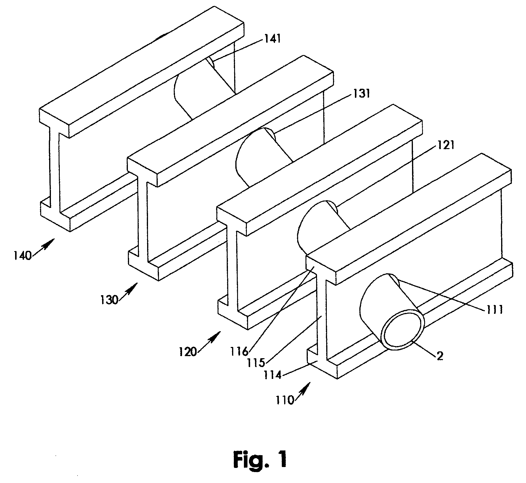
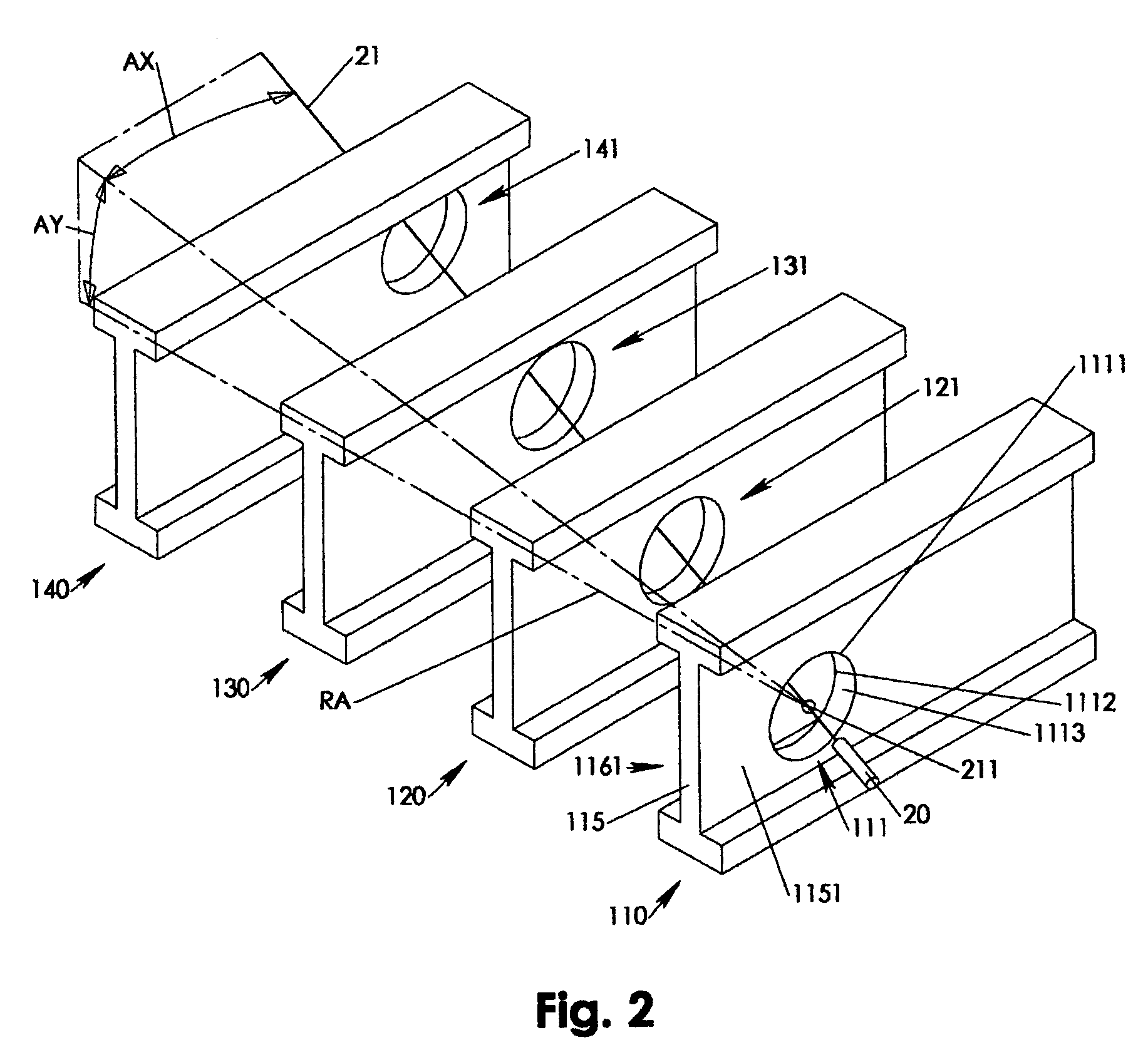
[0034]Referring to FIGS. 5–8, a laser marking device 60 includes an adjustable fixture 61 connected with a centering feature 62, which in turn holds a marking laser holder 66 via a horizontal angle gage 63 and a vertical angle gage 65. The adjustable fixture 61 has at least two spring loaded and oppositely expanding structures 613A, 613B each of which independently combined with a number of wall stops 611. As a result, the wall stops 611 are laterally forced against the cutout wall 1113 once the laser marking device 60 is inserted and released in the initial cutout 111.
[0035]The adjustable fixture 61 may additionally feature spring loaded counter stops 612 that press resiliently against the web back side 1161 while compensating for eventual burrs and other structural inconsistencies stemming from an imperfect cutting of the initial cutout 111. The forced contact between counter stops 612 and the web back side 1161 pulls the fixture 61 with the front stops 616 towards the web front ...
second embodiment
[0040]Referring to FIG. 9, a laser marking device 70 according to the invention is similar to the laser marking device 60 except that the laser marking device 70 additionally provides a holder 756 for the alignment laser 30. The alignment laser holder 756 is connected via an offset arm 751 to the vertical gage 75 such that both lasers 20, 30 are structurally coupled in their rotational movement around the vertical axis VA.
[0041]Alternatively, the offset arm 751 may be directly and only connected with the marking laser holder 76, which may couple both lasers 20, 30 in both their horizontal and vertical movements. In such case, the alignment beam 31 may coincide only with the vertical axis VA but not with the alignment origin 311, which may be negligible where vertical angle AY is only within a view degrees.
[0042]The laser marking device 70 differs from the laser marking device in as much as the laser marking device 70 may feature an level angle 717 guided in an angle guide 716 that i...
third embodiment
[0043]Referring to FIGS. 10–11, a laser marking device 80 according to the invention includes an alignment laser holder 863 rotationally guided in a vertical alignment gage 851 and pivoting around a top horizontal axis TH that substantially intersects with the vertical axis VA at the alignment origin 311. The vertical alignment gage 851 is together with the vertical marking gage 852 part of a rigid dual gage body 85 that is rotationally guided by the horizontal angle gage 83 and pivoting around the vertical axis VA. The separate vertical rotations of alignment laser holder 863 and marking laser holder 862 is synchronized via connecting rod 87 hinging on a top rod pin 865 of the alignment laser holder 863 and hinging on a bottom rod pin 864 of the marking laser holder 862. As a result, the first vertical offset VO1 of marking beam 21 and alignment beam 31 remains substantially constant irrespective the vertical angle AY.
[0044]The third embodiment exemplarily demonstrates a configurat...
PUM
 Abstract
Description
Claims
Application Information
 - R&D
- Intellectual Property
- Life Sciences
- Materials
- Tech Scout
- Unparalleled Data Quality
- Higher Quality Content
- 60% Fewer Hallucinations
Browse by: Latest US Patents, China's latest patents, Technical Efficacy Thesaurus, Application Domain, Technology Topic, Popular Technical Reports.
© 2025 PatSnap. All rights reserved.Legal|Privacy policy|Modern Slavery Act Transparency Statement|Sitemap|About US| Contact US: help@patsnap.com


