Universal card holder for electronic devices

a technology for electronic devices and card holders, applied in the direction of coupling device connections, instruments, other accessories, etc., can solve the problem of limit the number of such card holders, also referred to as extension slots

Inactive Publication Date: 2007-03-20
INTELLECTUAL VENTURES I LLC
View PDF5 Cites 5 Cited by
  • Summary
  • Abstract
  • Description
  • Claims
  • Application Information

AI Technical Summary

Benefits of technology

[0010]In an exemplary embodiment said guiding elements are split into upper and lower guiding element sections associated to said upper and lower slots, respectively. Said upper and lower guiding element sections are resiliently arranged on said left and said right lateral face, in a fashion to be movable independent of each other, such that only the guiding element section associated to a respective slot is pushed aside by an accessory card of first or second height h1 / h2 being inserted into that slot, such that said accessory card of first or second height can be received in that slot unobstructed by the associated guiding element section. This enables to provide a card holder with a height of the combined slot that is as small as possible. Providing extension slots with the minimal required height is advantageous and possibly even essential particularly in mobile devices with limited available space.
[0011]In an exemplary embodiment the card holder further comprises at least one resilient element arranged on the inner side of said top or said bottom face for spring-biasing accessory cards received in said card holder towards said bottom or said top face, respectively. This embodiment is particularly advantageous in cases where the height the of guiding elements adds up to the total height of the combined slot, and wherein this combined slot is though intended to accommodate only cards having more or less exactly the double height than single-height cards. The mechanical play can be eliminated for such cards, while the resilient element can be pushed aside similarly to the guiding elements when only single-height cards are used.
[0013]In an exemplary embodiment the guiding elements are constituted by spring-biased guiding rails, wherein the guiding rails are formed tapering towards the open front face of said housing. Implementing the guiding elements as rails is a simple and efficient method. The tapering, e.g. providing a wedge-shaped front end on the rails, is necessary in order to enable easy and smooth insertion of a card, for improving the usage comfort as well as avoiding damaging the card due to excessive necessary force.

Problems solved by technology

The number of such card holders, also referred to as extension slots, is always a limitation, particularly in mobile devices as laptops, PDAs and mobile phones.
Another problem related to such extension cards is that there are in some cases two form factors available for cards of the same type, such with single height and such with double height.

Method used


Image

  • Universal card holder for electronic devices
  • Universal card holder for electronic devices
  • Universal card holder for electronic devices

Examples


Embodiment Construction

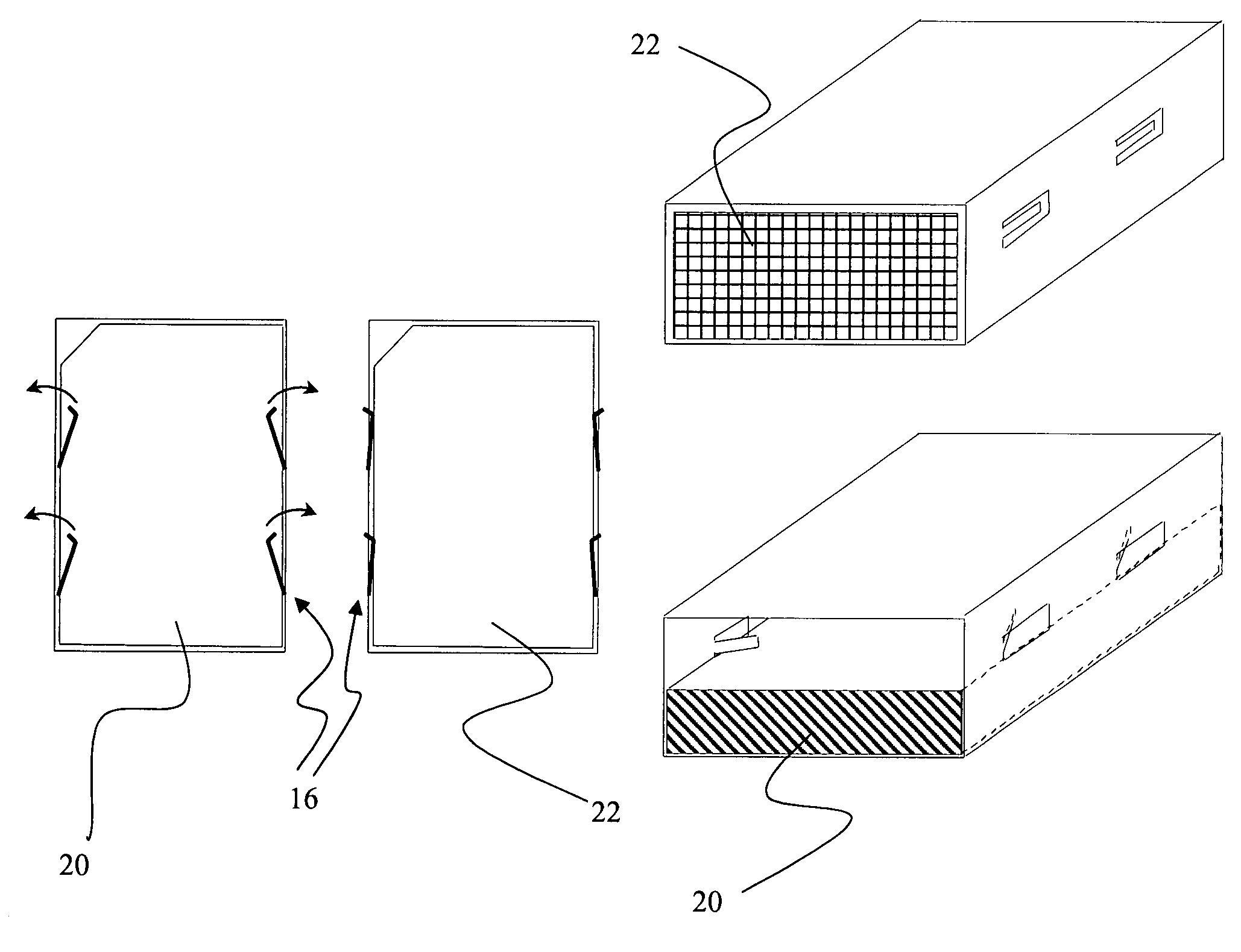
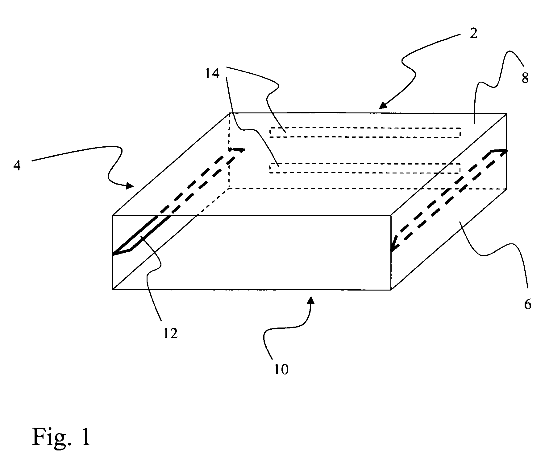
[0024]In FIG. 1 the principle of the card holder according to the invention is illustrated in a 3-dimensional view. An inventive card holder, i.e. its housing, is constituted by a back face 2, a left side face 4, a right side face 6, a top face 8 and a bottom face 10. It should be noted that the faces do not necessarily comprise complete surfaces, i.e. it is possible to provide them with cut-outs or recesses. In the variant depicted here two electrical interfaces 14 are arranged on the back face 2. However it is also possible to arrange them on the top and bottom faces 8, 10, or in any other suitable position, depending on the type of card that shall be connectable and the respective location of contacts on the card. On the side faces 4 and 6 guiding elements 12 are provided. These guiding elements 12 define upper and lower slots for receiving accessory cards.

[0025]Such cards that are suited to be accommodated in one of said slots are in the following referred to as “single-height c...


PUM


Abstract

A card holder for a mobile electronic device for receiving accessory cards, which includes a substantially cuboidal housing having an open front face for inserting accessory cards, the housing including a back face, a left and a right lateral face, and a top and a bottom face, at least two guiding elements protruding from the interior side of the left and right lateral faces, respectively, and extending parallel to and between said top and said bottom face. The guiding elements define an upper slot of a first height h1 between the top face and the guiding elements and a lower slot of a second height h2 between the bottom face and the guiding elements, for receiving accessory cards of first height h1 and second height h2, respectively, and the upper and the lower slots together define a combined slot for receiving an accessory card of a third height h3.

Description

FIELD OF THE INVENTION[0001]The present invention relates to a card holder for electronic devices and an electronic device equipped with such a card holder. The invention particularly relates to a card holder being able to receive up to two single-height accessory cards simultaneously, as well as one accessory card of substantially double height.BACKGROUND[0002]Particularly since the use of mobile electronic devices, ranging from laptop computers to small electronic devices like PDAs and mobile phones, holders for accessory cards have become widely used. There are mainly two types of such accessory cards which are intended to enhance the capabilities of an electronic device. Examples of the first type are memory cards like compact flash, MMC, SD cards or the like, which are used as portable memory devices for exchanging data. Another type that has become rather popular recently is related to wireless interface cards providing different wireless connection capabilities like Bluetooth...

Claims


Application Information

Patent Timeline
Patent Type & Authority Patents(United States)
IPC IPC(8): H01R13/60
CPCA45C11/18G06K7/0013G06K19/005G06K7/0043G06K7/006G06K7/0034A45C2011/188
Inventor WEINGART, PETERTHEIMER, WOLFGANGSCHINK, ROLANDSUONMAA, MIKA
Owner INTELLECTUAL VENTURES I LLC
Why Eureka
Try Eureka