Frequency mismatch compensation for multiuser detection

a multi-user detection and frequency mismatch technology, applied in the field of multi-user detection systems, can solve problems such as increased frame length, received signals drifting in phase rotation as frames, and situations becoming particularly problematic, so as to achieve the effect of not increasing the training overhead of the system

Active Publication Date: 2007-03-13
COLLISION COMM
View PDF15 Cites 3 Cited by
  • Summary
  • Abstract
  • Description
  • Claims
  • Application Information

AI Technical Summary

Benefits of technology

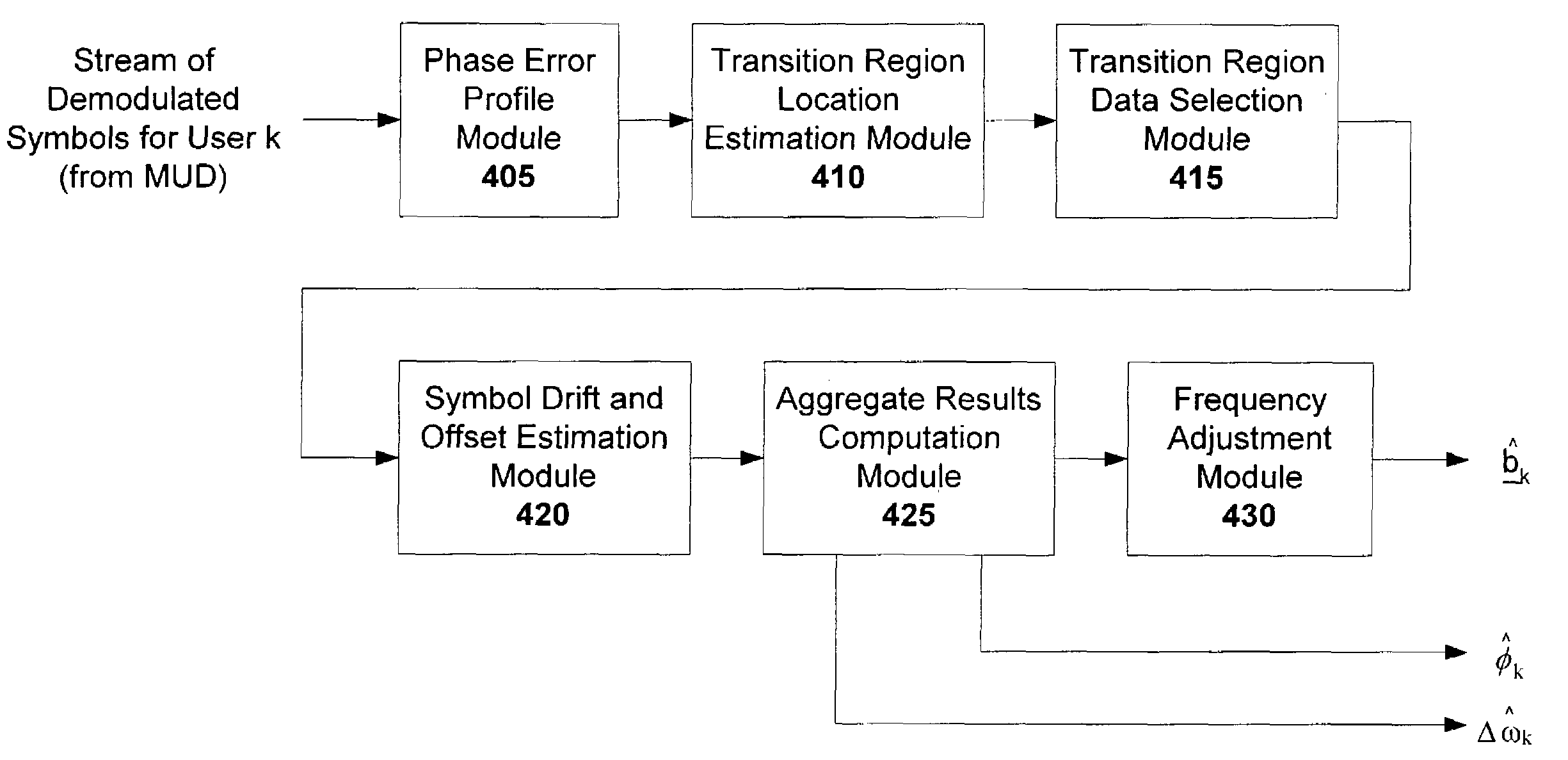
[0010]Using the techniques described herein, carrier frequency mismatch can be estimated and compensated for without increasing the training overhead of the system. Furthermore, carrier frequency mismatch estimation is generalized to the multiuser case in which there is a different carrier frequency mismatch between a particular receiver and each transmitter in the system.

Problems solved by technology

This situation becomes especially problematic as the frame length is increased.
In particular, mismatches between the transmitter and receiver carrier frequencies, which is common in all communications systems, cause the received signals to drift in phase rotation as the frame progresses.
This mismatch is most typically due to accuracy limitations of the local oscillators in both the transmitters and receivers, and can also be caused by Doppler shifts due to moving transmitters and / or receivers.
This same technique is not possible in a multiuser detection system because the received signal is composed of the superposition of each transmission signal as seen at the receiver, and the frequency mismatch is unique between the receiver and each transmitter.
This compensation technique for handling carrier mismatch drift, however, is associated with a number of disadvantages.
One of the more significant disadvantages is that the overhead of the system is increased.
This means that for a fixed signaling rate of the system, training data will replace the payload data, thereby decreasing throughput of payload data or decreasing the overall information carrying capacity of the channel.

Method used


Image

  • Frequency mismatch compensation for multiuser detection
  • Frequency mismatch compensation for multiuser detection
  • Frequency mismatch compensation for multiuser detection

Examples


Embodiment Construction

[0033]Embodiments of the present invention can be employed to solve the problem of poor performance of a MUD receiver when the parameter estimation module computing the S matrix has incorrectly estimated, or more commonly, has not attempted to estimate the carrier frequency difference between the receiver and each transmitter. The carrier frequency difference between the receiver and each transmitter is an important parameter influencing the shape of each waveform contributing to the S matrix. These estimates can be adjusted while the MUD receiver is working, to compensate for faulty estimates or a lack of individual estimates by the parameter estimation module. Note that if carrier frequency estimates are incorporated into the S matrix, then the S matrix will vary for each symbol estimate n. Therefore, the new S matrix will be a function of the current set of symbols being estimated (e.g., S(n)).

[0034]In accordance with the principles of the invention, estimates of the carrier freq...


PUM


Abstract

Techniques for compensating for frequency mismatch between transmitters and receivers of a multiuser communication system having a plurality of users are disclosed. In particular, the mismatch of carrier frequency estimates are estimated and compensated for each user of the system. This is accomplished without increasing the training overhead of the system. Symbol phase drift and offset is computed by estimating phase error profile parameters (e.g., slope and offset). The disclosed techniques may be used to correct for symbol rotation in any one decision region, or in neighboring decision regions.

Description

RELATED APPLICATIONS[0001]This application is a continuation-in-part of U.S. application Ser. No. 10 / 105,918, filed Mar. 25, 2002. In addition, this application is related to U.S. Pat. No. 6,947,502. This application is also related to U.S. Pat. No. 7,092,452. Each of these applications is herein incorporated in its entirety by reference.FIELD OF THE INVENTION[0002]The invention relates to multiuser detection systems, and more particularly, to carrier frequency mismatch compensation techniques for multiuser detection receiver applications.BACKGROUND OF THE INVENTION[0003]Receivers for digital communications systems are becoming available which can handle several transmissions simultaneously. Such receivers typically make use of multiuser detection, commonly referred to as MUD. Multiuser Detection is a means by which several signals either completely or partially occupying a single communications channel can be separated mathematically.[0004]To operate, a MUD receiver must have the r...

Claims


Application Information

Patent Timeline
IPC IPC(8): H04L27/06H04B1/707H04L25/03H04L27/00
CPCH04B1/7107H04L1/0048H04L1/005H04L25/03171H04L27/0014H04L1/06H04L2027/0067H04L2027/0055
Inventor MACLEOD, ROBERT BNIEDZWIECKI, JOSHUA DKARWEDSKY, KARI M
Owner COLLISION COMM
Why Eureka
Try Eureka