
Drip rate monitor for intravenous infusion set

a technology of drip rate monitor and intravenous infusion, which is applied in the field of drip rate monitor for use with intravenous infusion set, can solve the problems of reducing the flow of fluid, affecting the flow, and kinking of tubing,

Inactive Publication Date: 2007-03-13
GOLDBERG BARRY A +1
View PDF11 Cites 74 Cited by
  • Summary
  • Abstract
  • Description
  • Claims
  • Application Information

AI Technical Summary

Benefits of technology

[0009]Still further the present invention provides a method of monitoring the drip rate of an infusion fluid being administered by an intravenous infusion set comprising the steps of detecting the drops of infusion fluid being administered by the intravenous infusion unit, determining a first amount of time required to detect a first set of drops of infusion fluid having a predetermined number of dr

Problems solved by technology

After the drip rate of the fluid is initially set, patient movement can adversely affect the flow.
The tubing may become kinked by the patient rolling onto the tubing, thus reducing the flow of fluids.
Excessive movement by the patient may cause changes to the resistance dynamics of the tubing causing a steady stream of fluid to pass through the tube into the drip-chamber rather than at the desired drip rate.
Such changes in the flow of fluid when falling outside an acceptable range of drip rate variation can be dangerous to the patient, particularly when the change goes unnoticed for a length of time.
However, these devices are complicated, bulky and expensive.
Furthermore, none of the existing devices adequately alert the administrator of unacceptable variations in the drip rate of the fluids without first completely shutting down the flow.

Method used


Image

  • Drip rate monitor for intravenous infusion set
  • Drip rate monitor for intravenous infusion set
  • Drip rate monitor for intravenous infusion set

Examples


Embodiment Construction

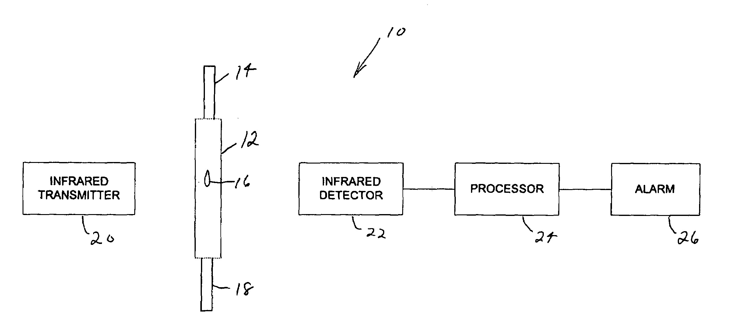
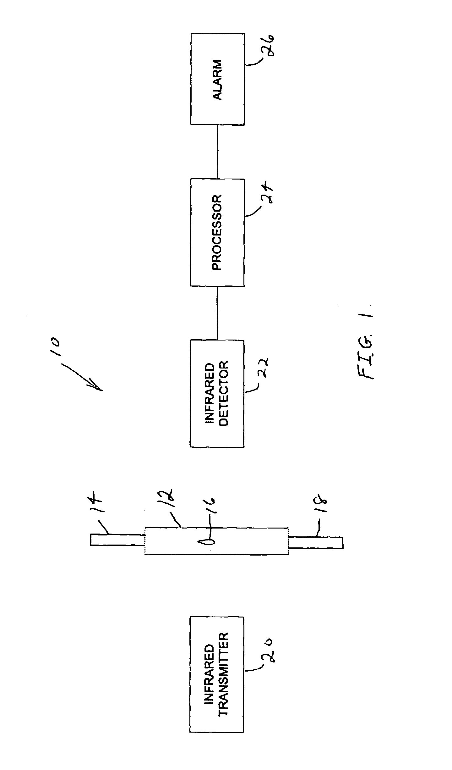
[0019]Referring to FIG. 1, a drip rate monitor 10 for monitoring the drip rate of an infusion fluid being administered by an intravenous infusion set according to one embodiment of the invention is shown. A drip chamber 12, which can be for example a macro or micro drip chamber, is part of an intravenous infusion set as is known in the art. An infusion fluid is supplied to drip chamber 12 by tubing 14 a drop at a time as is shown by drop 16. The infusion fluid is provided to the patient by intravenous tubing 18. An infrared transmitter 20 and an infrared detector 22 are positioned on opposite sides of drip chamber 12 to detect drop 16 as it falls in drip chamber 12. When drip rate monitor 10 is in use, infrared transmitter 20 is always on and transmitting infrared light energy. The difference in the amount of infrared light energy received by infrared receiver 22 that occurs when drop 16 is in between infrared transmitter 20 and infrared transmitter 22, indicates the detection of a ...


PUM


Abstract

An apparatus for monitoring the drip rate of an infusion fluid being administered by an intravenous infusion set comprising a housing, drop sensor, alarm and processor. The housing is attachable to a drip chamber, and the drop sensor is positioned in the housing to detect drops of the infusion fluid being administered by the intravenous infusion set. The processor determines a first amount of time required for the drop sensor to detect a first set of drops of infusion fluid having a predetermined number of drops, determines a second amount of time required for the drop sensor to detect a second set of drops of infusion fluid having the predetermined number of drops, compares the second amount of time to a range of time having a minimum that is less than the first amount of time and a maximum that is greater than the first amount of time, and activates the alarm if the second period of time is not within the range of time.

Description

CROSS-REFERENCE TO RELATED APPLICATION[0001]This application is related to and claims priority to U.S. Provisional Application Ser. No. 60 / 426,249, filed Nov. 14, 2002, entitled METHOD AND APPARATUS FOR MONITORING VARIATIONS IN THE FLOW OF FLUIDS THROUGH AN ADMINISTRATION SET, the entirety of which is incorporated herein by reference.STATEMENT REGARDING FEDERALLY SPONSORED RESEARCH OR DEVELOPMENT[0002]Not ApplicableFIELD OF THE INVENTION[0003]The invention relates generally to infusion systems, and more particularly, to a drip rate monitor for use with an intravenous infusion set.BACKGROUND OF THE INVENTION[0004]An intravenous infusion set is used to provide liquid intravenously to patients. An elevated drip-chamber is typically provided as part of a gravity feed administration set with tubing connected to the top and bottom of the chamber. The administrator of the fluids can control the flow of fluids by adjusting a clamp attached to the tubing that pinches the tubing thereby restr...

Claims


Application Information

Patent Timeline
IPC IPC(8): G08B21/00A61M5/168
CPCA61M5/1689Y10S128/13
Inventor GOLDBERG, BARRY A.LAI, SHU CHUNG
Owner GOLDBERG BARRY A
Learn More