
Apparatus for digital-analog conversion of a signal

a technology of analog and digital, applied in the field of analog analog and digital analog conversion, can solve the problems of reducing output dynamics, switching noise, and reducing dynamic, and achieve the effect of less affected by nois

Active Publication Date: 2007-03-06
STMICROELECTRONICS SRL
View PDF7 Cites 2 Cited by
  • Summary
  • Abstract
  • Description
  • Claims
  • Application Information

AI Technical Summary

Benefits of technology

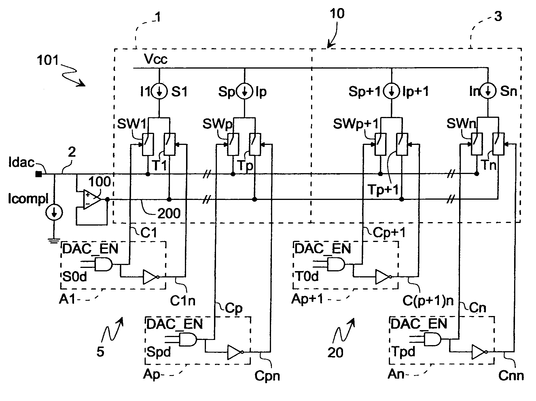
The present invention provides an apparatus for the digital-analog conversion of a signal that reduces noise. This is achieved by using a first circuit to produce a first output signal based on a desired output signal and a second circuit to produce a second output signal based on an external variable signal. The first and second output signals are combined to form the final output signal, resulting in a less affected signal due to switching noise. The apparatus includes current sources, switches, and a control circuit to generate control signals for the switches. The invention also includes a phase-locked loop circuit that includes a voltage controlled oscillator and a fractional frequency divider to further reduce noise. Overall, the invention provides an improved apparatus for digital-analog conversion with reduced noise.

Problems solved by technology

One problem that troubles such converters lies in the decoupling of the current sources that diminishes the dynamic and static linearity of the converter, produces switching noise (presence of spikes of current in output) and decreases the output dynamics.
The request of an additional current source can, however, degrade the dynamic performance of the converter since the input and output switchings of the current sources on the calibration ratio introduce spurious phenomena at the calibration frequencies in the output spectrum of the converter.
In practice these spurious phenomena comprise additional dynamic components coming from dynamic decouplings among the arrays of current sources that are used every time.

Method used


Image

  • Apparatus for digital-analog conversion of a signal
  • Apparatus for digital-analog conversion of a signal
  • Apparatus for digital-analog conversion of a signal

Examples


Embodiment Construction

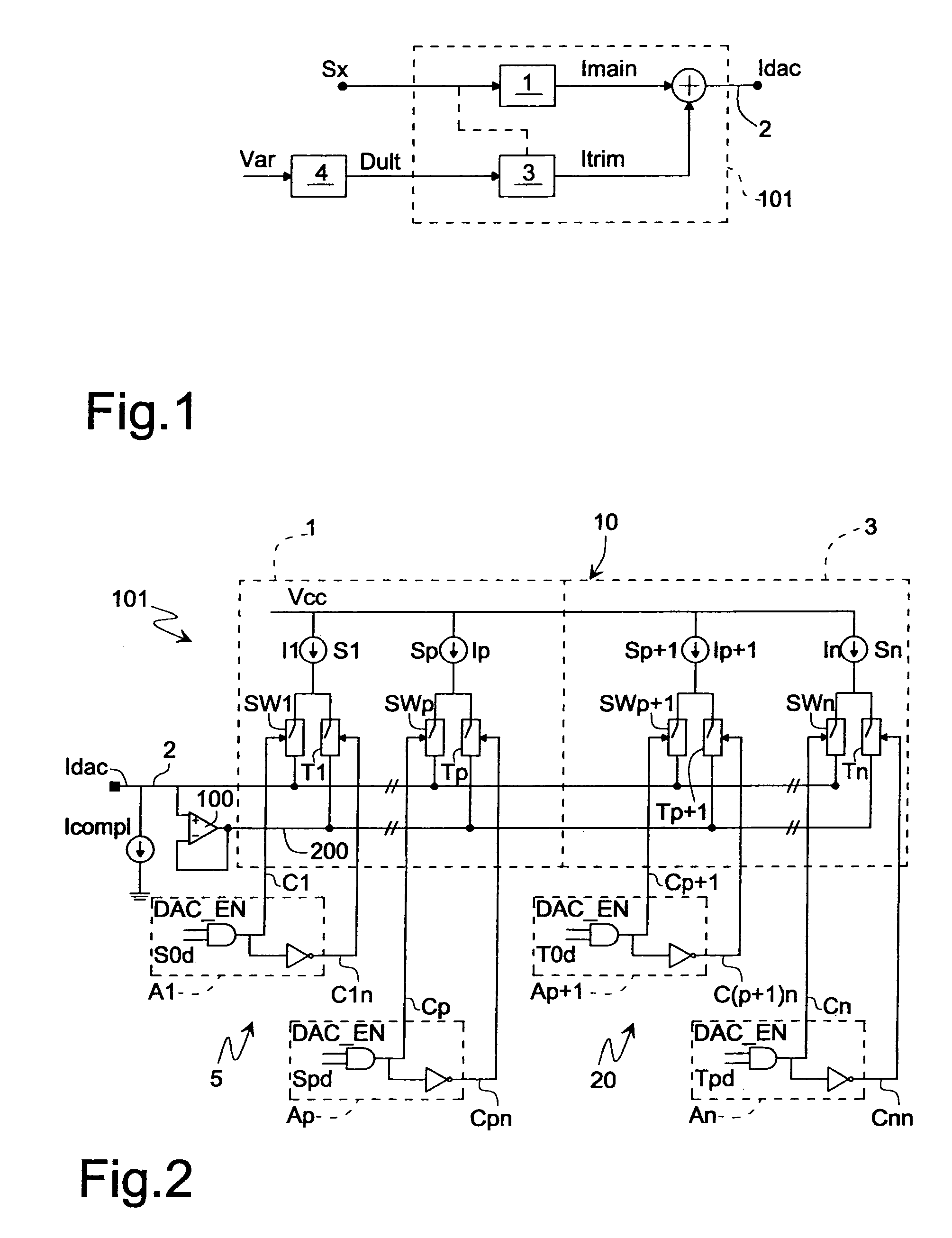
[0025]With reference to FIG. 1 an apparatus according to one embodiment of the present invention for the conversion of a digital signal Sx into a analog signal Idacis is shown. The apparatus includes a converter block 101 having a first circuit block 1 suitable for supplying a current signal Imain on an output line 2 starting from the digital input signal Sx and a second circuit block 3 suitable for supplying a current signal Itrim on the output line 2 in reply to a further digital input signal Dult. The latter is produced by means such as a circuit 4 in response to external input variables Var where with external variables environmental variables are indicated, such as the temperature or variables relating to the particular application in which the apparatus is used as preset values of voltage or of current, and so on. The signal Dult can be formed by an enabling signal En according to a first embodiment of the invention or by a digital correction signal Tx according to a second em...


PUM


Abstract

An apparatus for the conversion of a digital input signal into an analog output signal, the apparatus including a first circuit receiving the digital input signal that is representative of the analog output signal and suitable for producing a first signal on an output line, and a second circuit for supplying a second signal on the output line, in response to a further digital signal. The further digital signal is a function of external variables, and the union of the first and second signal on the output line forms the analog output signal.

Description

BACKGROUND OF THE INVENTION[0001]1. Field of the Invention[0002]The present invention refers to an apparatus for the digital-analog conversion of a signal.[0003]2. Description of the Related Art[0004]Currently we are in the presence of a growing demand, above all in the market of radio communications, for high speed and high resolution digital-analog type converters (DAC), that is converters capable of converting a digital word, normally a word in code, into an analog signal.[0005]An architecture that has been used to produce high speed and high resolution DACs includes an array of current sources. The digital-analog converter receives a digital input word that represents a desired output current and the current sources are selectively switched into an output to provide for the desired output current. Such types of converters have been used above all for driving resistive loads without the need for a voltage buffer.[0006]One problem that troubles such converters lies in the decoupli...

Claims


Application Information

Patent Timeline
Patent Type & Authority Patents(United States)
IPC IPC(8): H03M1/66
CPCH03M1/1061H03M1/745
Inventor BRUNO, ANGELACALI', GIOVANNIPALLESCHI, ANTONIO
Owner STMICROELECTRONICS SRL
Learn More