
Device and process for determining the position of an engine

a technology of internal combustion engine and position determination, which is applied in the direction of process and machine control, electrical control, instruments, etc., can solve the problem that the internal combustion engine has a tendency to oscillate before stopping, and achieve the effect of moderate cos

Inactive Publication Date: 2007-02-27
SIEMENS VDO AUTOMOTIVE CORP
View PDF7 Cites 70 Cited by
  • Summary
  • Abstract
  • Description
  • Claims
  • Application Information

AI Technical Summary

Benefits of technology

[0015]The purpose of the invention is to eliminate this drawback for a moderate cost and by preserving the compatibility with the preceding generations of sensors, in other words by detecting only the shifting of teeth (respectively, hollows), in addition to the direction of rotation, regardless of the latter.
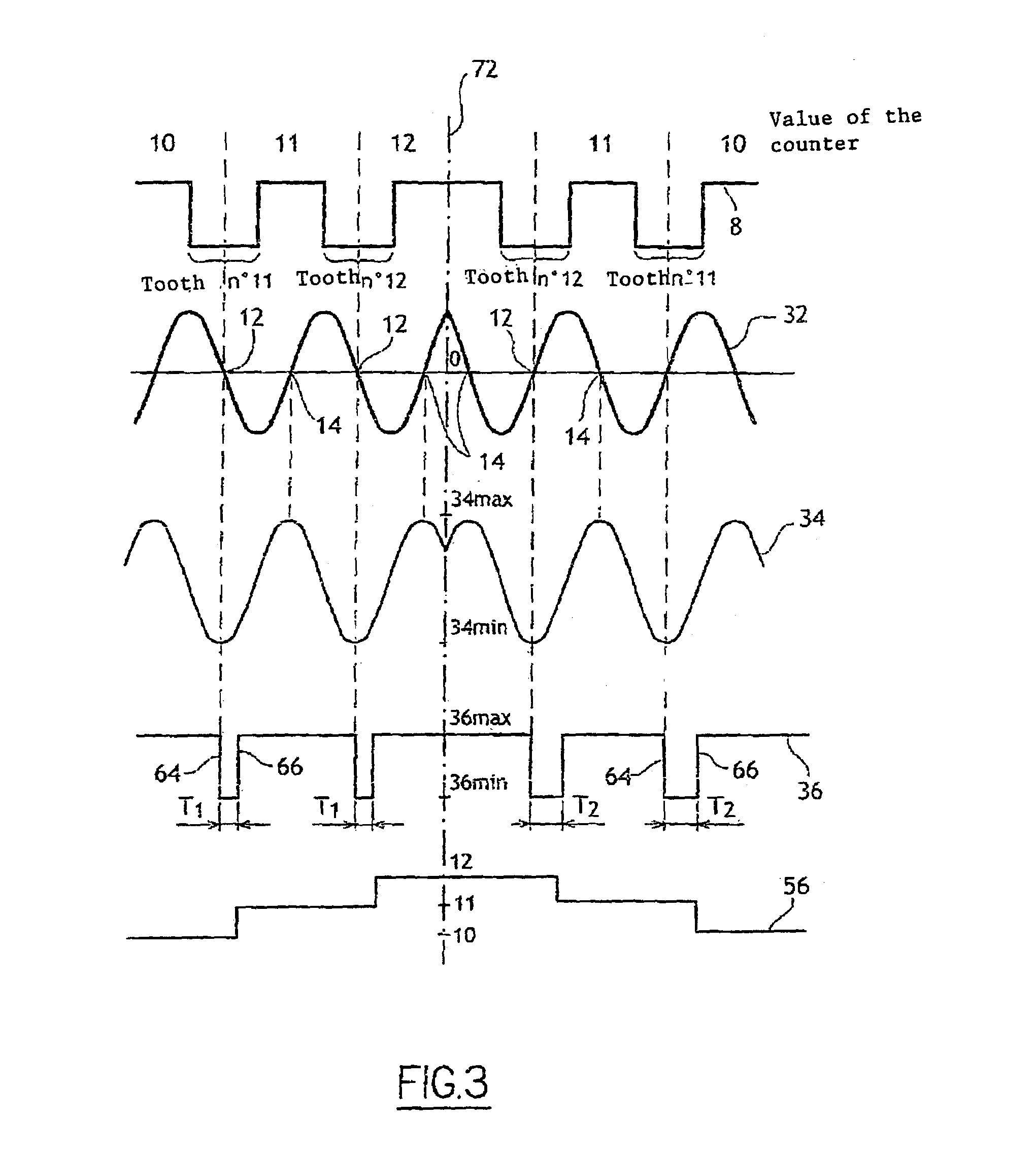
[0033]Thus, owing to variations in the air gap, temperature, etc., the derivatives that can undergo over time the fourth signal and the fifth signal are attenuated. The device thus has great precision and great strength.
[0048]The precision of the detection of the position of the rotary element is thus improved.

Problems solved by technology

However, as mentioned above, the internal combustion engine has a tendency to oscillate before stopping.

Method used


Image

  • Device and process for determining the position of an engine
  • Device and process for determining the position of an engine
  • Device and process for determining the position of an engine

Examples


Embodiment Construction

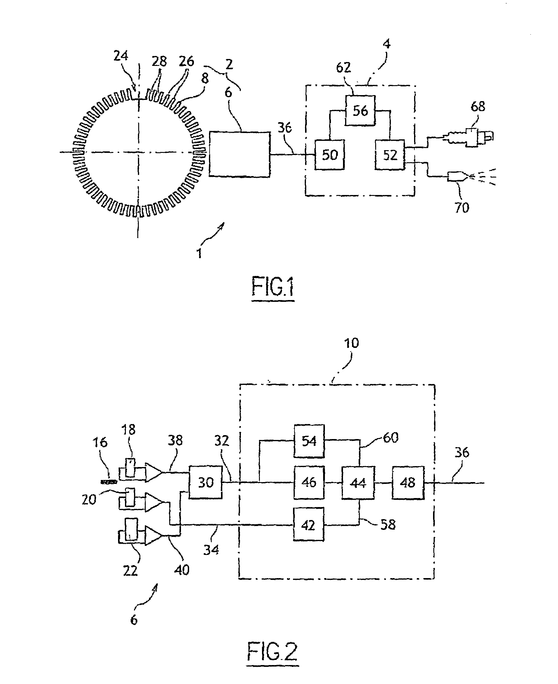
[0053]FIG. 1 illustrates a device 1 that essentially comprises a sensor 2 and an engine control unit 4.

[0054]Sensor 2 comprises a rotary part 8 that is integral with the crankshaft of the engine and a fixed part 6 that is intended to detect the movements of rotary part 8. Fixed part 6 is shown in more detail in FIG. 2.

[0055]Rotary part 8 comprises a ferromagnetic disk 8 that consists of a succession of sixty teeth 26 and sixty hollows 28 that are distributed uniformly, such that teeth 26 (respectively hollows 28) are placed at the periphery of disk 8 every six degrees, which defines a rotation increment of the crankshaft. In fact, two teeth were removed in disk 8 so as to reference a reference position 24 of the crankshaft. Another number of teeth and hollows is also possible without thereby exceeding the scope of this invention.

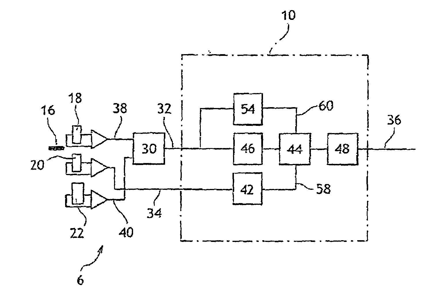
[0056]Fixed part 6 comprises a magnet, three Hall effect probes or identical magnetoresistive probes of type 18, 20, 22, a subtractor assembly 30 and an ana...


PUM


Abstract

Device for determining the position of an engine includes:a sensor that has a rotary part and a fixed part, whereby said fixed part comprises:elements (for generating a first signal based on the position of the rotary part relative to the fixed part),Second elements for generating a second phase-shifted signal relative to the first signal,elements for comparing the value of the second signal to a reference value,elements for detecting at least one characteristic event on the first signal, for generating a third signal of binary type, and for alternating the binary signal from a first value to a second after detection of at least one of the characteristic events if the result of the comparison is positive,engine control elements that include members for detecting the alternations of third signal and a counter.

Description

BACKGROUND OF THE INVENTION[0001]The invention relates to a device and a process for determining the position of an internal combustion engine comprising a rotary element.[0002]It is useful to know with precision the position of an internal combustion engine, in particular so as to improve its start-up and more specifically to reduce the start-up time, and even to allow the direct start-up of the engine without a starter. Actually, a better knowledge of the position of the engine makes it possible to select cylinders that are to be supplied with fuel, to determine the optimum amount of fuel to be injected, as well as the optimum ignition time.DESCRIPTION OF THE RELATED ART[0003]Already known is a device that comprises:[0004]A sensor that delivers a signal that takes on discrete values and that comprises a rotary part and a fixed part, whereby said rotary part is linked to the rotary element and comprises a number of essentially identical reference points that are offset angularly by...

Claims


Application Information

Patent Timeline
Patent Type & Authority Patents(United States)
IPC IPC(8): F02D43/04G01M15/06F02D41/34G06F19/00
CPCF02D41/009
Inventor TEULINGS, WILLEMCANTIE, FREDERIC
Owner SIEMENS VDO AUTOMOTIVE CORP
Learn More