Fluid-powered inspection camera

a fluid-powered inspection and camera technology, applied in closed circuit television systems, picture signal generators, television systems, etc., can solve the problems of not being able to easily access the source of electrical power at the site of the furnace, and not being able to have unnecessary power cables

Inactive Publication Date: 2007-02-27
MIRION TECH IMAGING LLC
View PDF15 Cites 4 Cited by
  • Summary
  • Abstract
  • Description
  • Claims
  • Application Information

AI Technical Summary

Benefits of technology

[0005]In this particular embodiment, the fluid is compressed air. However, in other embodiments the device may utilize other fluids, such as nitrogen, etc. The inspection device may be a video camera, a television camera, an infrared camera, or some other type of camera or device. The eye may include a lens, and the flow of fluid discharged from the tube open end is directed so as to cool the eye, and to protect the eye from contaminants in the environment. In another embodiment, the device includes an eductor, which is operatively arranged such that fluid discharged from the motor outlet passes through the eductor and entrains ambient air from within the chamber into the flow discharged through the tube open end. Compressed air supplied from the source may be combined with air discharged from the motor outlet upstream of the eductor. The flow of compressed air is arranged to cool the imaging device, as well as the eye.

Problems solved by technology

In some applications, notably steel mills, a source of electrical power may not be readily available at the site of the furnace, or it may not be desirable to have unnecessary power cables in such environment.

Method used


Image

  • Fluid-powered inspection camera
  • Fluid-powered inspection camera
  • Fluid-powered inspection camera

Examples


Embodiment Construction

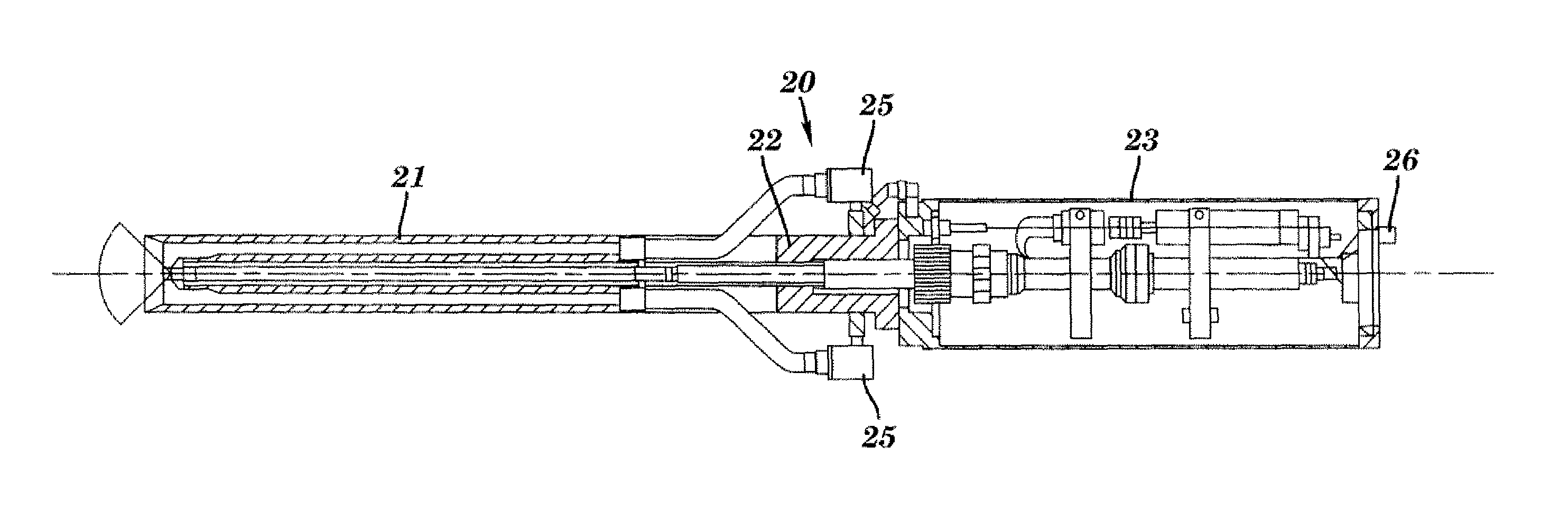
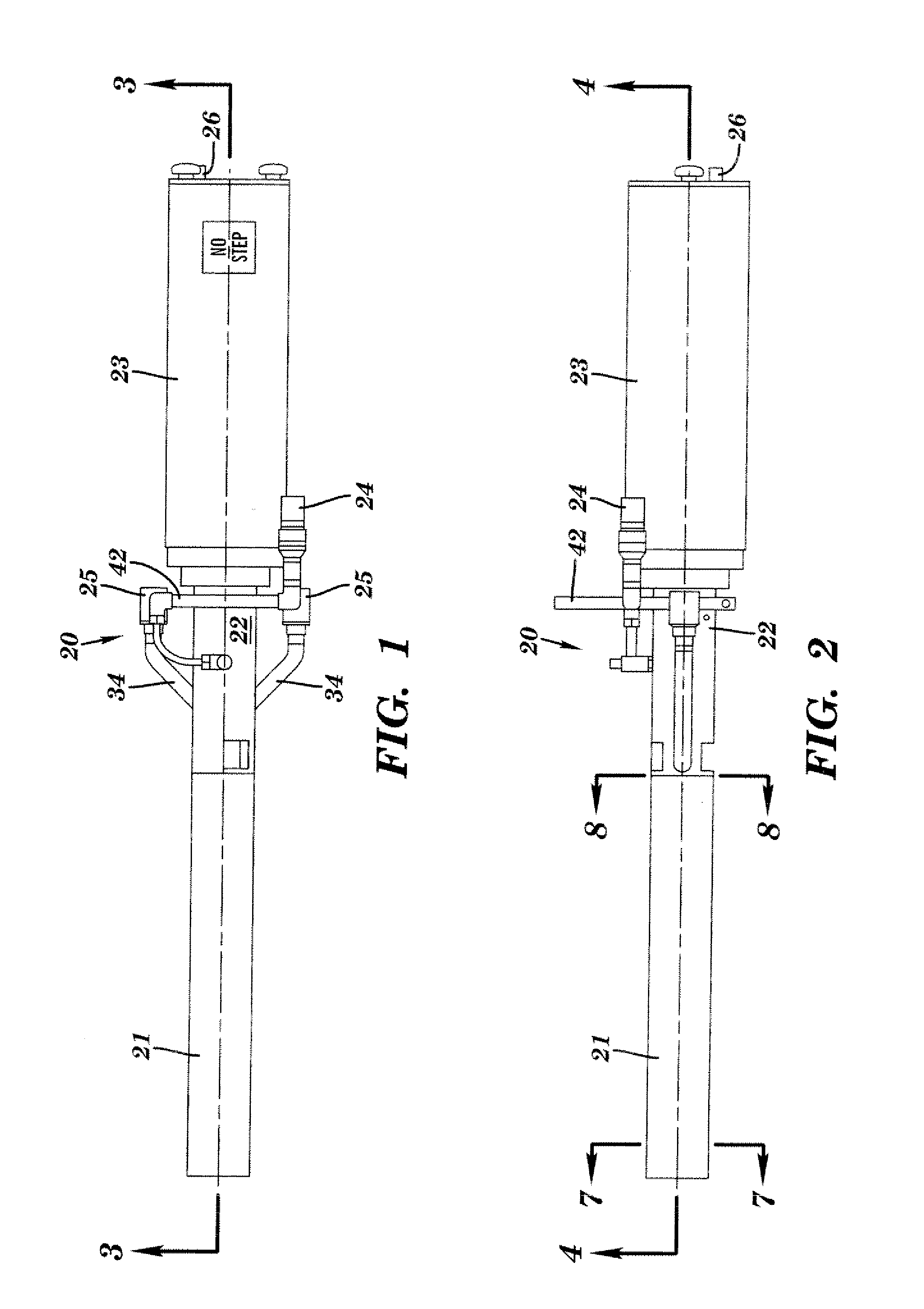
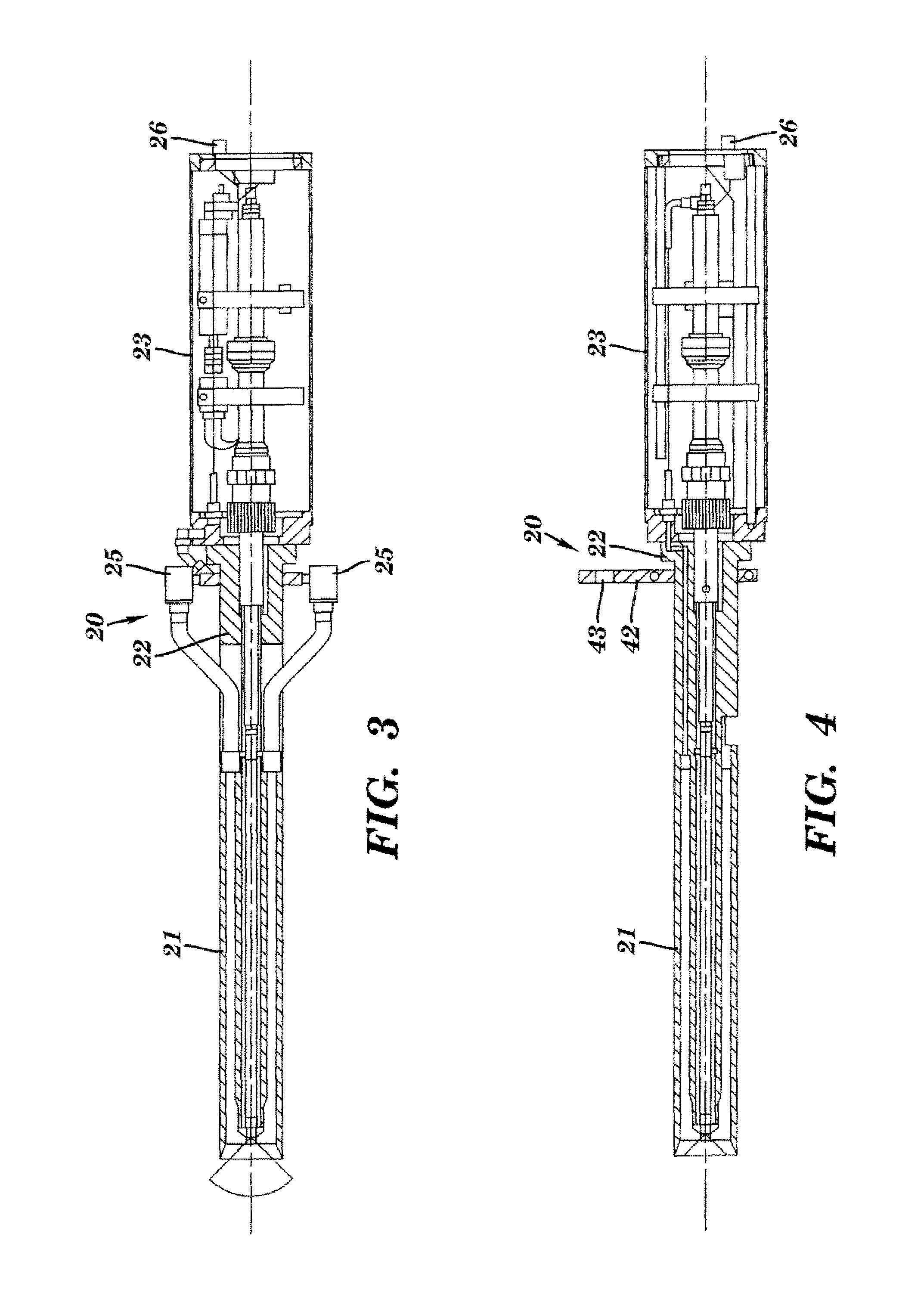
[0016]At the outset, it should be clearly understood that like reference numerals are intended to identify the same structural elements, portions or surfaces, consistently throughout the several drawing figures, as such elements, portions or surfaces may be further described or explained by the entire written specification, of which this detailed description is an integral part. Unless otherwise indicated, the drawings are intended to be read (e.g., cross-hatching, arrangements of parts, proportion, degree, etc.) together with the specification, and are to be considered a portion of the entire written description of this invention. As used in the following description, the terms “horizontal,”“vertical,”“left,”“right,”“up” and “down,” as well as adjectival and adverbial derivatives thereof (e.g., “horizontally,”“rightwardly,”“upwardly,” etc.), simply refer to the orientation of the illustrated structure as the particular drawing figure faces the reader. Similarly, the terms “inwardly...


PUM


Abstract

A fluid-powered inspection camera adapted to be operated in a contaminated environment where an electric power supply is not readily available includes a housing having a tubular shell terminating at an open end. An imaging device has a portion arranged within the tubular shell in a spaced relation so as to define an annular chamber therebetween. The imaging device has an eye positioned adjacent to the open end of the body. A compressed fluid-powered motor is arranged within the body and has a compressed fluid inlet adapted to be connected to a suitable source of compressed fluid and also has a compressed fluid outlet. A generator is operatively coupled to the compressed fluid-powered motor and arranged within the body to electrically power the imaging device in proportion to the rate of fluid flow passing through the motor. Compressed fluid discharged from the compressed fluid-powered motor outlet passes through the annular chamber and is discharged through the open end of the body. The compressed fluid supplied to the fluid-powered motor powers and cools the imaging device while keeping clean the eye of the imaging device.

Description

FIELD OF THE INVENTION[0001]The present invention relates generally to the field of cameras, and more particularly, to a fluid-powered inspection camera capable of operating in environments where electrical power is not readily available.BACKGROUND OF THE INVENTION[0002]Inspection and surveillance cameras are in widespread use today. These are sometimes used in or around hazardous and / or contaminated environments, such as to monitor and view the ignition and / or combustion of a furnace. As used herein, a “contaminated” environment typically contains airborne dust or particulate material that obscures a normal view of an object to be seen. In some applications, notably steel mills, a source of electrical power may not be readily available at the site of the furnace, or it may not be desirable to have unnecessary power cables in such environment. However, compressed air is generally available at various locations near the furnace.[0003]Hence, it would be generally desirable to provide ...

Claims


Application Information

Patent Timeline
Patent Type & Authority Patents(United States)
IPC IPC(8): H04N5/225
CPCH04N5/2252H04N2005/2255H04N23/555H04N23/51
Inventor WOODSTOCK, PETER
Owner MIRION TECH IMAGING LLC
Why Eureka
Try Eureka