Impedance sensing screen pointing device

a technology of impedance sensing and screen, which is applied in the direction of static indicating devices, optical radiation measurement, instruments, etc., can solve the problems of erratic operation or total failure of the mouse, damage or deterioration of the surface of the mouse pad, and degradation of the ease of rotation of the contact roller

Inactive Publication Date: 2007-02-27
PIXART IMAGING INC
View PDF20 Cites 14 Cited by
  • Summary
  • Abstract
  • Description
  • Claims
  • Application Information

AI Technical Summary

Problems solved by technology

Among the shortcomings are deterioration of the mouse ball or damage to its surface, deterioration or damage to the surface of the mouse pad, and degradation of the ease of rotation of the contact rollers because of accumulation of dirt or lint, and because of wear.
These problems can contribute to erratic operation or total failure of the mouse.

Method used


Image

  • Impedance sensing screen pointing device
  • Impedance sensing screen pointing device
  • Impedance sensing screen pointing device

Examples


Embodiment Construction

[0013]In the following detailed description of the preferred embodiments, reference is made to the accompanying drawings, which form a part hereof, and in which is shown by way of illustration specific embodiments in which the invention may be practiced. It is to be understood that other embodiments may be utilized and structural or logical changes may be made without departing from the scope of the present invention. The following detailed description, therefore, is not to be taken in a limiting sense, and the scope of the present invention is defined by the appended claims.

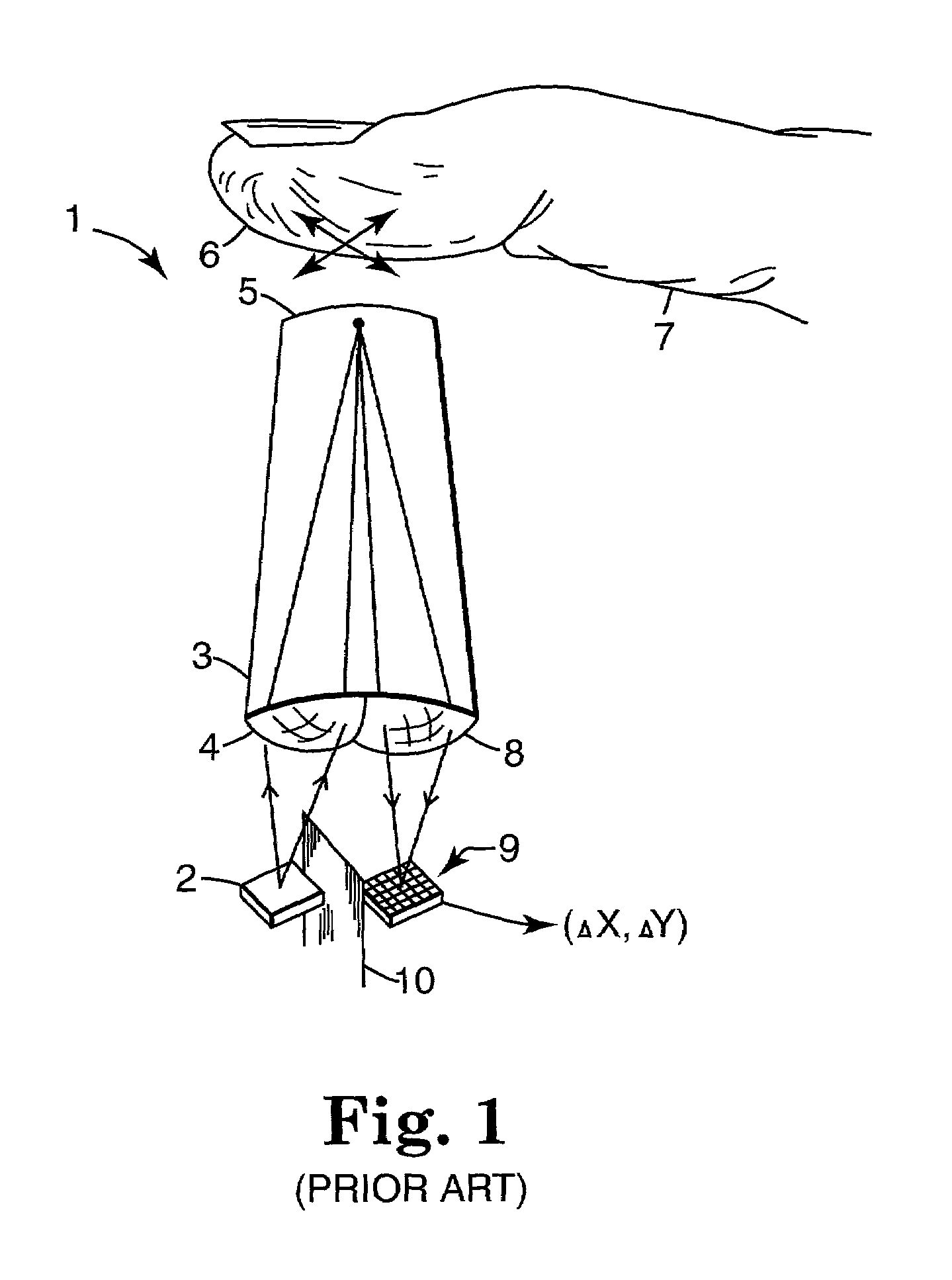
[0014]FIG. 1 shows a simplified representation of a side view of a prior art motion detection arrangement 1 suitable for tracking the movement of a human finger 7 pressed against a surface 5 of a transparent stud 3. A motion detection arrangement like that shown in FIG. 1 is described in detail in the above-incorporated U.S. Pat. No. 6,057,540 (the '540 patent). The operation of motion detection arrangement 1 is...


PUM


Abstract

An apparatus for controlling the position of a screen pointer for an electronic device having a display screen includes a plurality of sensing elements against which a portion of the tip of a human digit may be placed. A controller coupled to each of the sensing elements senses an electrical property at each of the sensing elements. The controller is configured to generate pixel values representing the portion of the tip of the digit placed against the sensing elements based on the sensed electrical property at each of the sensing elements, and generate movement data based on a comparison of successively generated sets of the pixel values. The comparison includes comparing a first one of the sets with at least one pixel shifted version of a second one of the sets. The movement data is indicative of motion of the tip of the digit across the sensing elements.

Description

REFERENCE TO RELATED PATENTS[0001]This Application is related to the subject matter described in the following U.S. patents: U.S. Pat. No. 5,578,813, filed Mar. 2, 1995, issued Nov. 26, 1996, and entitled FREEHAND IMAGE SCANNING DEVICE WHICH COMPENSATES FOR NON-LINEAR MOVEMENT; U.S. Pat. No. 5,644,139, filed Aug. 14, 1996, issued Jul. 1, 1997, and entitled NAVIGATION TECHNIQUE FOR DETECTING MOVEMENT OF NAVIGATION SENSORS RELATIVE TO AN OBJECT; and U.S. Pat. No. 5,786,804, filed Oct. 6, 1995, issued Jul. 28, 1998, and entitled METHOD AND SYSTEM FOR TRACKING ATTITUDE. These three patents describe techniques of tracking position movement and computer pointing devices. Those techniques are a component in a preferred embodiment described below. Accordingly, U.S. Pat. Nos. 5,578,813, 5,644,139, and 5,786,804 are hereby incorporated herein by reference. This application is also related to the subject matter described in U.S. Pat. No. 6,057,540, filed Apr. 30, 1998, issued May 2, 2000, and ...

Claims


Application Information

Patent Timeline
Patent Type & Authority Patents(United States)
IPC IPC(8): G09G5/00G06F3/033G06F3/044
CPCG06F3/03547G06F3/044G06F2203/0338G06F3/0443H01L27/14678
Inventor GORDON, GARY B.WALLACE, HUGH
Owner PIXART IMAGING INC
Why Eureka
Try Eureka