
Offshore floating dock

a floating dock and dock technology, applied in the field of boat docks, can solve the problems of long waiting list for moorings, no floating dock is adapted for offshore locations, and previous attempts to use offshore devices to solve the space problems associated with crowded harbors are largely unsuccessful

Inactive Publication Date: 2007-02-27
BRINE WILLIAM H
View PDF40 Cites 18 Cited by
  • Summary
  • Abstract
  • Description
  • Claims
  • Application Information

AI Technical Summary

Benefits of technology

[0006]It is a further object of this invention to provide an offshore boat dock that allows boats moored to the dock to adjust to the prevailing wind and water conditions.
[0007]It is a further object of this invention to provide a versatile, modular boat docking system.

Problems solved by technology

Virtually all harbors and their potential customers have the same problem, namely, a long waiting list for moorings.
However, none of these floating docks are adapted for offshore locations.
Prior to now, previous attempts to use offshore devices to resolve the space problems associated with crowded harbors are largely unsuccessful, particularly for harbors that have a lot of traffic or are located on a narrow waterway.
The limitations and value of such devices are known, as are the additional problems they cause in the process.
Furthermore, since only one boat can be moored to such devices, the maximum safe mooring density is quite low.
However, each one of these offshore devices has inherent problems.
Although Loverich's line potentially could provide for temporary offshore mooring, Loverich's offshore line does not provide sufficient means for protecting the boats from damaged caused by adjacently moored boats or from rough or varying water activity.
Lacy's offshore device has similar problems and is somewhat impractical.
Lacy's device would be expensive to make and install at least because it utilizes blocks of cement weighing two tons each as anchors.
The devices of Hallsten, Jones et al., Atlas, Trautwein, and Culley are all somewhat complex and expensive to make.
More importantly, the devices and the boats moored to the devices are subject to damage associated with varying weather and current conditions because they are anchored in a fixed directional position.

Method used


Image

  • Offshore floating dock
  • Offshore floating dock
  • Offshore floating dock

Examples


Embodiment Construction

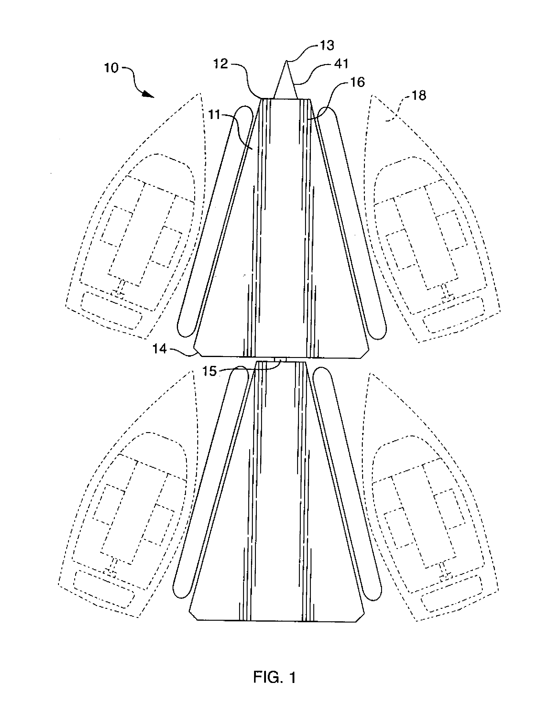
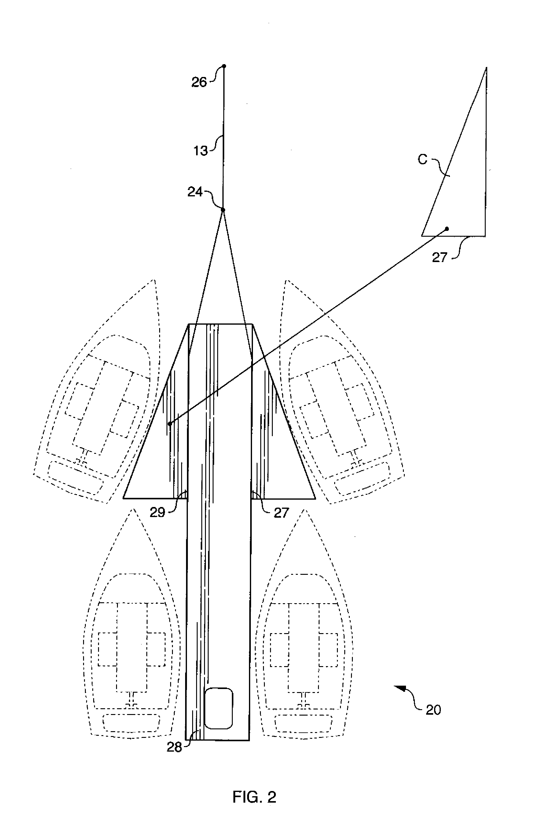
[0027]The invention features a boat docking system designed to accommodate a greater number of boats in a given harbor than would normally be allowable in view of coastline space constraints. Only one anchor is needed to maintain the docking system.

[0028]The preferred docking unit of the invention is preferably, although not limited to, about twenty feet long and holds two or more boats in a manner so that the boats are held in position into the wind when tied to the floating dock. Each dock is preferably angled because it is easier for a sailboat to tie on to an angled dock rather than a straight dock or mooring because the wind tends to push the boat into a bumpered dock causing undesirable, sudden motion of the boat, its passengers, and its contents. FIGS. 1–3 show three slightly different embodiments, generally referred to as docking units 10, 20, and 30, respectively, of the docking system of the invention, each providing for two to four mooring stations. A boat is moored using...


PUM


Abstract

The docking system of the invention comprises: at least one docking unit having an axis to which at least two boats may be docked offshore; at least one buoyant members coupled to docking unit; and at least one anchoring member adapted to anchor the platform to a substrate; wherein the docking unit is adapted to directionally adjust to changes in prevailing wind and water flow.

Description

FIELD OF THE INVENTION[0001]This invention relates to boat docks and more specifically to an offshore floating dock.BACKGROUND OF THE INVENTION[0002]Over the past ten to twenty years, the availability of open boat dock space has risen to a premium. Virtually all harbors and their potential customers have the same problem, namely, a long waiting list for moorings. In many instances, the actual wait time is as long as a person's lifetime. Floating docks that attached to fixed docks or otherwise to the shoreline to increase the length of fixed docks are known and widely used in the art. Examples of such floating docks are described in U.S. Pat. No. 5,915,325 to Gerber; U.S. Pat. No. 6,003,464 to Long; U.S. Pat. No. 5,911,542 to Obrock et al.; and U.S. Pat. No. 6,205,945 B1 to Passen et al. However, none of these floating docks are adapted for offshore locations.[0003]Prior to now, previous attempts to use offshore devices to resolve the space problems associated with crowded harbors ar...

Claims


Application Information

Patent Timeline
Patent Type & Authority Patents(United States)
IPC IPC(8): B63B35/44E02B3/00B63B59/02E02B3/06
CPCE02B3/064B63B21/50B63B35/38Y02A10/11
Inventor BRINE, WILLIAM H.
Owner BRINE WILLIAM H
Learn More