Rotationally molded subterranean tank with riser

a technology of subterranean tanks and risers, which is applied in the field of subterranean tanks, can solve the problems of corroding metal tanks, concrete tanks may crack or leak, and are generally heavy and difficult to transport and install, so as to improve durability and insulating qualities, improve load transfer, and improve adaptability

Inactive Publication Date: 2007-02-20
TANK HLDG CORP
View PDF14 Cites 14 Cited by
  • Summary
  • Abstract
  • Description
  • Claims
  • Application Information

AI Technical Summary

Benefits of technology

[0008]Applicant has thus recognized a need for a subterranean tank and riser assembly with greater adaptability to height variances at the site, for a tank assembly which provides improved durability and insulating qualities, for a vessel having consistency of wall thickness throughout, for improved load transfer regarding the weight of the earth over the vessel after it is buried, for a lightweight but structurally enhanced cover, for a complemental fitting between the cover and the vessel or riser which promotes positioning of the cover and securement to either the vessel or a riser, and for isolated inlet and outlet passages. These needs have been largely met by the subterranean tank and riser of the present invention.
[0009]The subterranean tank hereof broadly includes a vessel having spaced and isolated inlet and outlet passages and at least one and preferably a plurality of openings, a cover having upper and lower walls, and a riser especially configured for ease of attachment to the vessel and to the cover and having radially extending substantially horizontal flanges to enable trimming of the riser wall to various intermediate lengths but still enabling the remaining portion of the riser to receive the cover and couple to the tank opening. The vessel may be advantageously formed by rotational molding whereby a vessel wall of substantially capacity (e.g., 1500 gallons) may be formed in a single molding operation, and has a vessel wall which is of a corrugated, substantially parabolic shape which includes a plurality of ribs. The parabolic shape of the vessel wall is preferably provided both along the upper wall in a substantially transverse direction to the longitudinal axis and in the end walls in the longitudinal direction. The ribs alternate with arcuate, substantially flat surfaced vessel wall sections, the ribs being oriented substantially transverse to the longitudinal axis of the vessel along the arcuate top wall portion and in parallel planes to the longitudinal axis at the opposite axially spaced ends of the vessel. The rounded ribs are designed to maximize the modulus of the wall, and the large radii of the ribs enable the vessel to be rotationally molded with a uniform and consistent wall thickness. The arcuate, and most preferably parabolic top wall portion is preferably provided with portals surrounding and defining openings adjacent each end wall section at the highest part of the top wall portion to receive the covers thereon, and the vessel may be provided with a divider permanently fused to the vessel wall in the interior liquid receiving chamber oriented transverse to the longitudinal axis to divide the chamber into two compartments. The portals preferably including frustoconical rims which both help to distribute loads placed on the cover and limit stress concentrations as well as facilitating receipt of the covers thereon.
[0010]The cover is provided of double walled construction for improving durability, leak resistance and thermal insulating properties. The cover includes a plurality of circumferentially spaced, radially inwardly projecting lugs for bayonet-type locking engagement with receptacles on the rim of the vessel surrounding the opening. Further, the cover most preferably is provided with a plurality of circumferentially spaced depressions in the upper wall to facilitate fastening of the cover to the rim of the vessel around each of the openings by mechanical fasteners such as self-tapping screws. These depressions in the upper wall are fused during molding with the lower wall to enhance the strength of the cover around its circumferentially extending margin. The lower wall has a circumferentially extending frustoconical surface proximate the margin which aids in positioning the cover onto the rim of the portal and in the distribution of loads onto the vessel. In addition, a plurality of radially extending circumferentially spaced indentations are formed in the lower wall of the cover which are fused with the adjacent upper wall. These indentations provide additional strength for the cover to resist loads placed on the upper wall and help the cover to resist deformation of the rim of the portal due to horizontal forces such as impacts from machinery or thermal stresses.

Problems solved by technology

These tanks are generally heavy and difficult to transport and install.
Over time, the concrete tanks may crack or leak, and the metal tanks may corrode.
While the riser shown in U.S. Pat. No. 6,047,724 is designed for use with other risers to provide a suitable depth or height adjustability, it does not admit for adjustments in height less than the axial length of the riser.
That is to say, the construction of riser of the U.S. Pat. No. 6,047,724 necessitates that risers of a variety of different lengths be available on site to permit the cover to be placed at grade level as each riser is of a definite length and not capable of adaptation to the differences of depth as the tank is buried and covered with earth discoverable only after installation is complete.
Furthermore, the covers used with the tanks of this type have traditionally been of concrete or metal which are both expensive and heavy.

Method used


Image

  • Rotationally molded subterranean tank with riser
  • Rotationally molded subterranean tank with riser
  • Rotationally molded subterranean tank with riser

Examples


Embodiment Construction

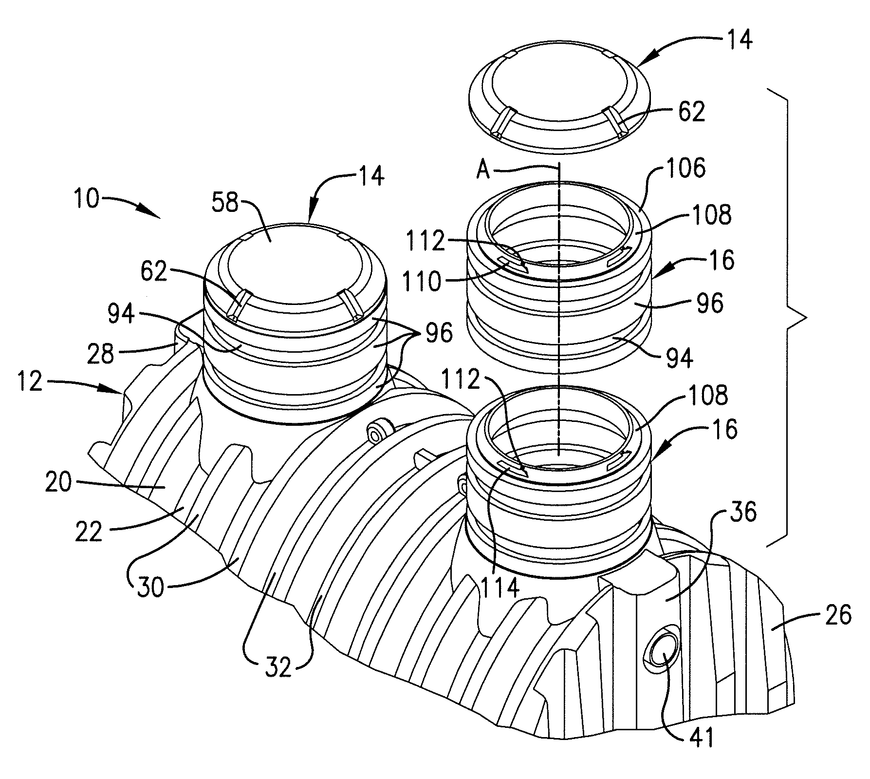
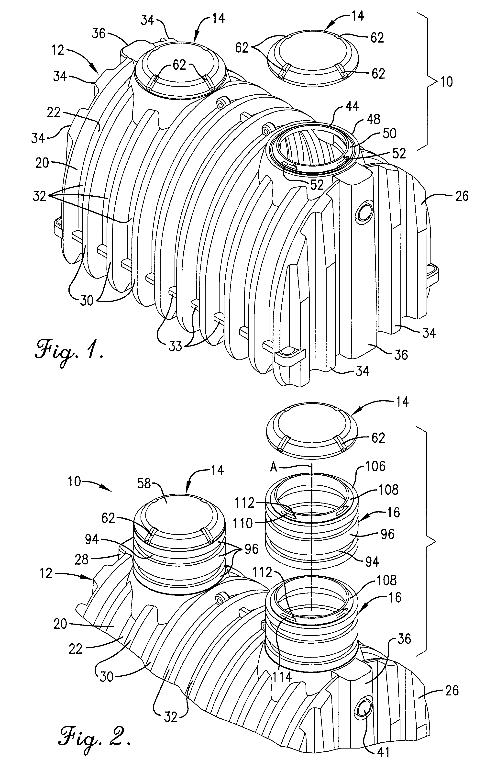
[0022]Referring now to the drawings, a subterranean tank assembly 10 in accordance with the present invention broadly includes a vessel 12 and a cover 14, and as shown in FIG. 2, a riser 16 which may be coupled to the vessel 12 intermediate the vessel and the cover 14. A plurality of risers 16 may be connected together to provide a riser assembly 18 which effectively raises the placement of the cover 14 relative to the top of the vessel 12.

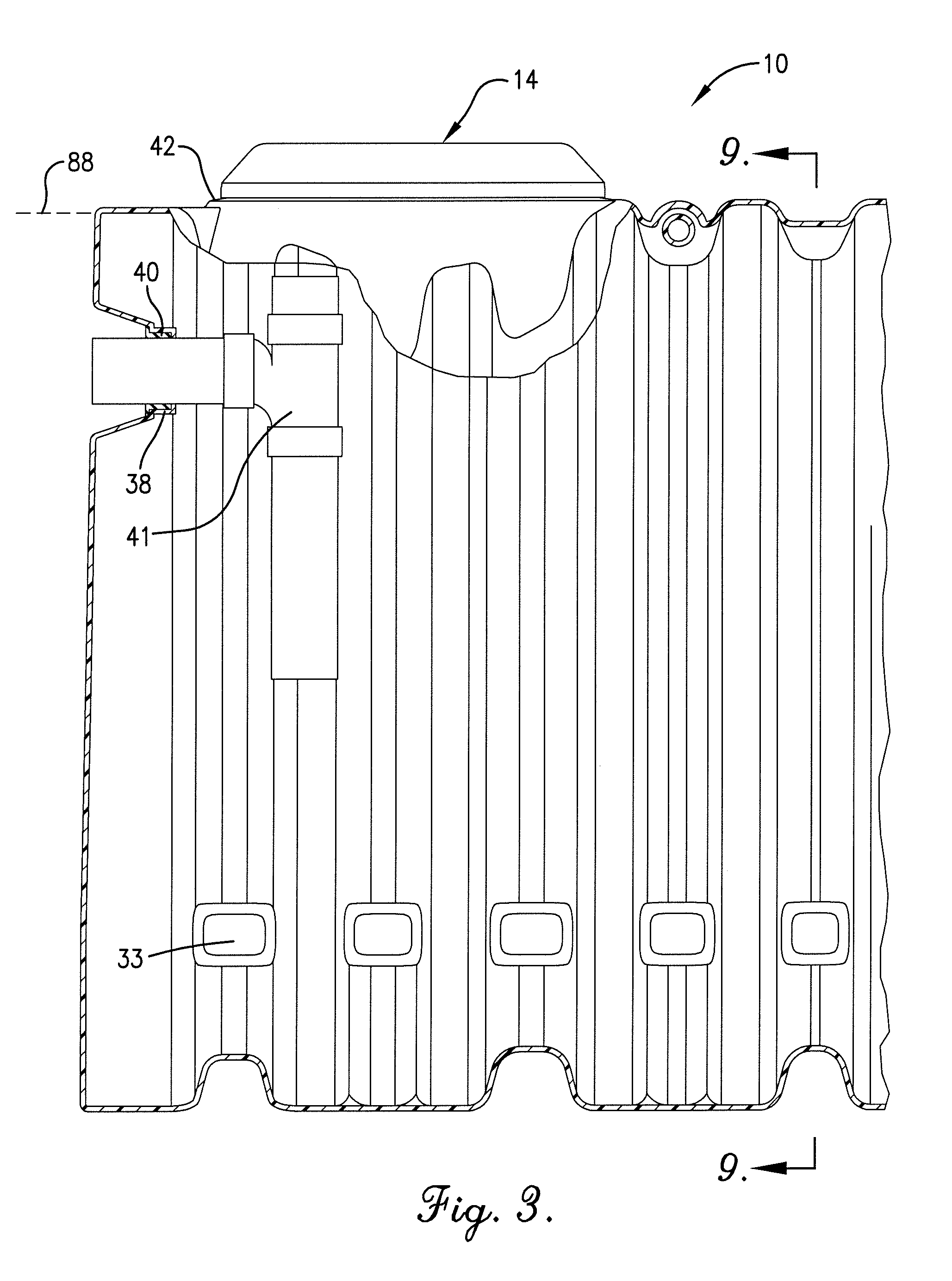
[0023]In greater detail, the vessel 12 as shown in FIGS. 1 and 2, in a partial sectional view in FIG. 3, and in vertical section in FIG. 9 includes a vessel wall 20 defining a chamber 21 and having a parabolic top wall portion 22, a substantially horizontal bottom wall portion 24, and upright end walls 26 and 28. The vessel 12 extends longitudinally between the end walls. The vessel wall 20 is preferably rotationally molded of synthetic resin such as high-density linear polyethylene. The top wall portion 22 is substantially parabolic in configurat...


PUM

PropertyMeasurementUnit
heightaaaaaaaaaa
heightaaaaaaaaaa
lengthaaaaaaaaaa

Abstract

A subterranean tank assembly is provided which broadly includes a vessel, a cover, and a riser which is configured to permit the riser to be adjusted in axial length at the job site. The riser is configured to permit coupling of the cover to the topmost connector portion thereof and to a portal of the vessel. The riser includes a plurality of substantially parallel, axially spaced circumferentially extending flanges which mate with the rim of the portal surrounding the opening, whereby the flanges may be fastened to the vessel in lengths intermediate to the initial length of the riser without the necessity of altering the tank or the cover.

Description

BACKGROUND OF THE INVENTION[0001]1. Field of the Invention[0002]The present invention is broadly concerned with subterranean tanks for receiving sewage or serving as a cistern for holding water which are rotationally molded of synthetic resin material. More particularly, the present invention is concerned with a tank of the foregoing type provided with parabolic wall construction and a portal arrangement for accomodating a uniquely and complementally configured cover or a synthetic resin riser which is constructed in such a manner that it may trimmed in multiple locations along its axial length while retaining wall strength and the ability to couple to the tank and receive a cover thereon.[0003]2. Description of the Prior Art[0004]As used in this application, “subterranean tank” refers to vessels for containing liquid which are intended to be substantially completed covered with earth so as to lie below grade. These subterranean tanks are commonly used in residential and light comme...

Claims


Application Information

Patent Timeline
Patent Type & Authority Patents(United States)
IPC IPC(8): B65D88/76B29C41/04B65D90/02B65D90/10
CPCB65D88/06B65D90/105B65D90/027B65D88/76B29C41/04
Inventor BOLZER, TODDROGERS, JEFFREY T.
Owner TANK HLDG CORP
Why Eureka
Try Eureka