
Elevator control having independent safety circuits

a safety circuit and lift technology, applied in the field of elevator installation, can solve the problem of blocking the travel of cars that are coupled to this safety circui

Inactive Publication Date: 2007-02-20
TK ELEVATOR INNOVATION & OPERATIONS GMBH
View PDF9 Cites 43 Cited by
  • Summary
  • Abstract
  • Description
  • Claims
  • Application Information

AI Technical Summary

Benefits of technology

The invention is a safety device for elevator installations that reduces mutual hindering of cars and allows for decoupling of car control from the state of the car doors and shaft doors. It achieves this by using at least two safety circuits that can independently block the travel of cars. The safety circuits have monitoring elements connected in series, so that the travel of the car is blocked as soon as one of its car doors or one of the shaft doors situated in its serving region is opened. The invention also allows for the opening of car doors in different shaft regions, without affecting the other cars. Overall, the invention provides a simple and effective solution for elevator safety.

Problems solved by technology

If one of these shaft doors is opened, only the travel of cars that are coupled to this safety circuit is blocked.
If a shaft door is opened in the upper shaft region, this merely has the consequence that the safety circuit associated with this shaft door responds, so that the cars that are coupled to this safety circuit are blocked in their travel, but not the cars that have no coupling with respect to this safety circuit.

Method used


Image

  • Elevator control having independent safety circuits
  • Elevator control having independent safety circuits
  • Elevator control having independent safety circuits

Examples


first embodiment

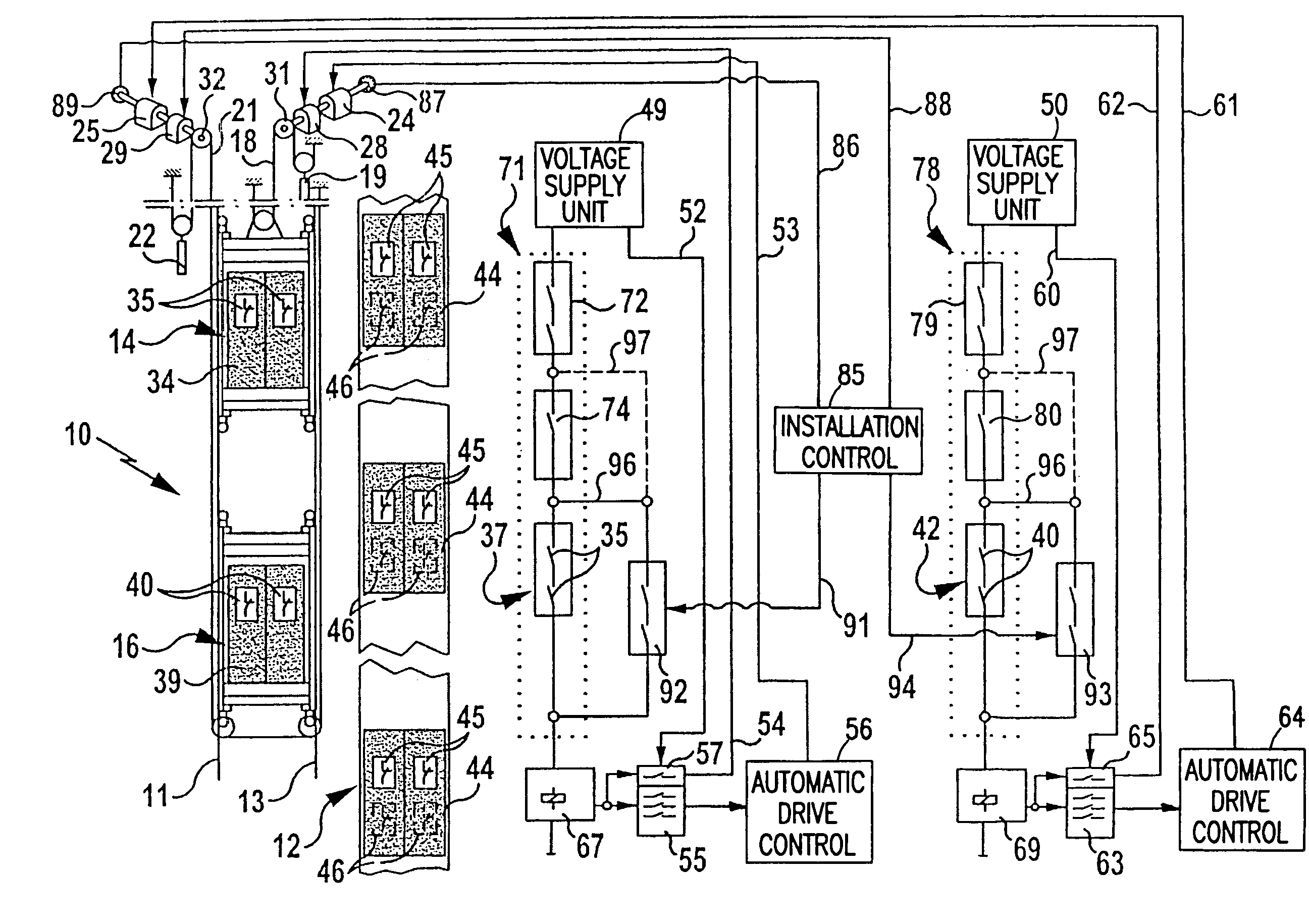
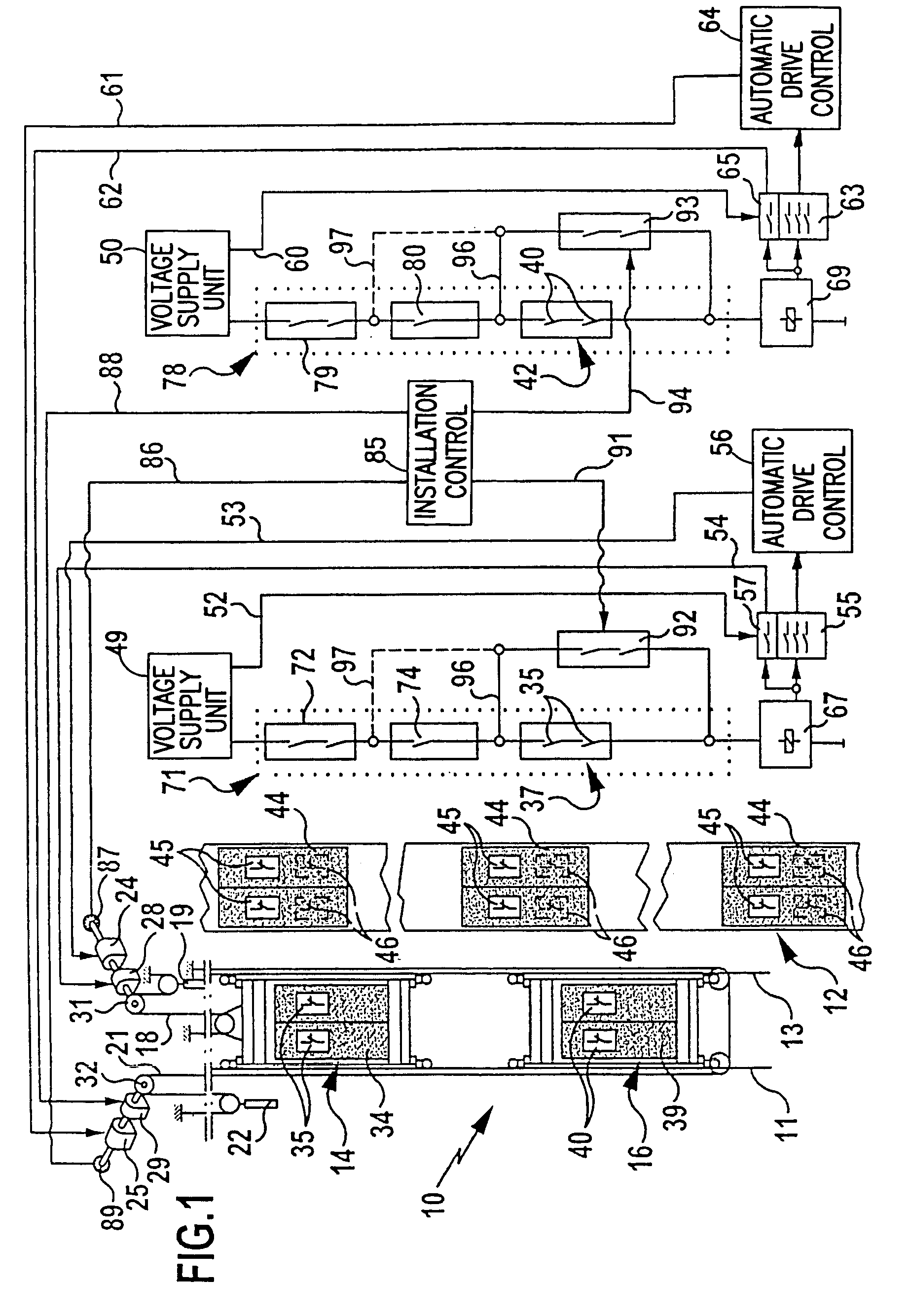
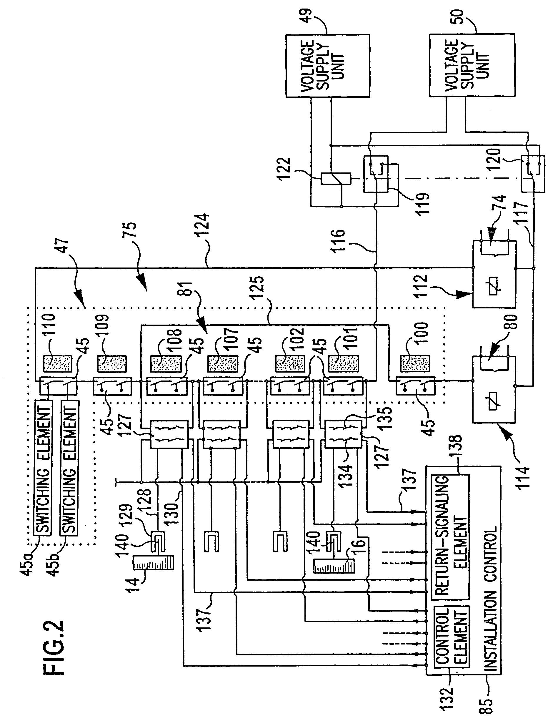
[0042]In FIGS. 1 and 2, an elevator installation according to the invention is represented in a greatly schematized form and designated overall by the reference numeral 10. It comprises two cars disposed one above the other in a shaft 12, specifically an upper car 14 and a lower car 16, which can be made to travel individually up and down along a common traveling path on guides 11, 13. To achieve a better overview, in the drawing the shaft 12 is shown offset in relation to the two cars 14 and 16.

[0043]The upper car 14 is coupled to a counterweight 19 via a suspension cable 18, and the lower car 16 is coupled to a counterweight 22 via a suspension cable 21. Each car 14 and 16 has a separate drive associated with it in the form of an electric drive motor 24 and 25, respectively, and in each case a separate brake 28 and 29, respectively. The drive motors 24 and 25 in each case drive a traction sheave 31 and 32, respectively, over which the suspension cables 18 and 21 are led.

[0044]The ...

second embodiment

[0087]In FIG. 3, an elevator installation according to the invention is schematically represented and provided overall with the reference numeral 150. This is configured largely identically to the elevator installation 10 explained above with reference to FIGS. 1 and 2. Therefore, the same reference numerals as in FIGS. 1 and 2 are used for identical components in FIG. 3. To avoid repetition, reference is made in this respect to the full content of the statements made above.

[0088]In the case of the elevator installation 150 represented in FIG. 3, the upper car 14 has a proximity switch 152, the switching contacts 153 of which are integrated into the shaft monitoring circuit 72 of the safety chain 71 associated with the upper car 14, the switching contacts 153 being connected in series with further switching contacts, known per se, of the safety circuit 72.

[0089]The actuation of the proximity switch 152 takes place by means of a switching roller 154, which is mounted on the outside o...


PUM


Abstract

An elevator installation with at least one shaft having a plurality of shaft doors is provided. At least two cars disposed one above the other travel up and down in the shaft. Each car has at least one car door. A safety device is provided for blocking the travel of the cars when the shaft doors or car doors are open. The safety device has at least two independent safety circuits, each having at least one shaft door and / or car door associated with it. Travel of at least one car can be blocked by means of the safety circuits.

Description

[0001]This application is a continuation of international application number PCT / EP2003 / 004487 filed on Apr. 30, 2003.[0002]The present disclosure relates to the subject matter disclosed in international application number PCT / EP2003 / 004487 of Apr. 30, 2003, which is incorporated herein by reference in its entirety and for all purposes.BACKGROUND OF THE INVENTION[0003]The invention relates to an elevator installation with at least one shaft, in which at least two cars disposed one above the other can be made to travel up and down, the shaft having a plurality of shaft doors and the cars respectively comprising at least one car door, and with a safety device for blocking the travel of the cars when the shaft doors or car doors are open.[0004]The invention also relates to a method for controlling an elevator installation with at least one shaft, in which at least two cars disposed one above the other can be made to travel up and down, the shaft having a number of shaft doors and the c...

Claims


Application Information

Patent Timeline
Patent Type & Authority Patents(United States)
IPC IPC(8): B66B9/00B66B1/18B66B1/14B66B1/24B66B13/14B66B13/22B66B13/24
CPCB66B9/00B66B13/22B66B13/143B66B11/0095B66B13/24
Inventor MEISSNER, WOLFGANGNUEBLING, WALTER
Owner TK ELEVATOR INNOVATION & OPERATIONS GMBH
Learn More