Elevator installation and method for controlling an elevator installation
a technology for elevators and installation methods, applied in the direction of elevators, transportation and packaging, building lifts, etc., can solve the problem of blocking the travel of cars that are coupled to this safety circui
- Summary
- Abstract
- Description
- Claims
- Application Information
AI Technical Summary
Benefits of technology
Problems solved by technology
Method used
Image
Examples
first embodiment
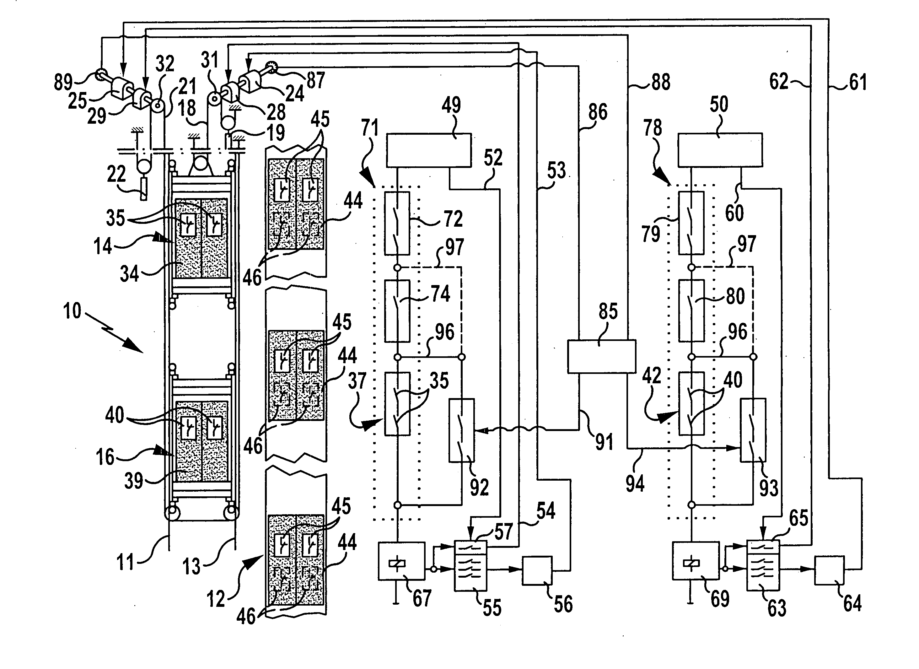
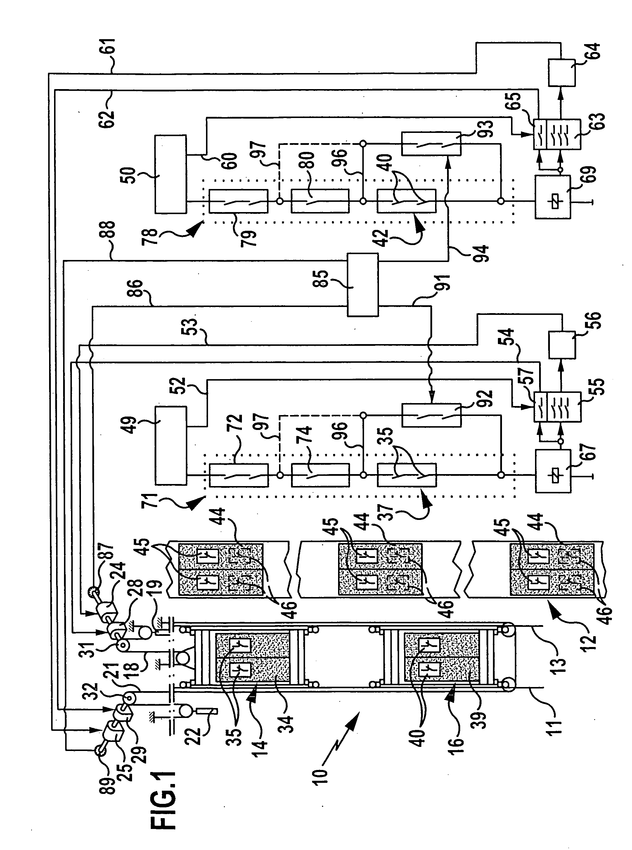
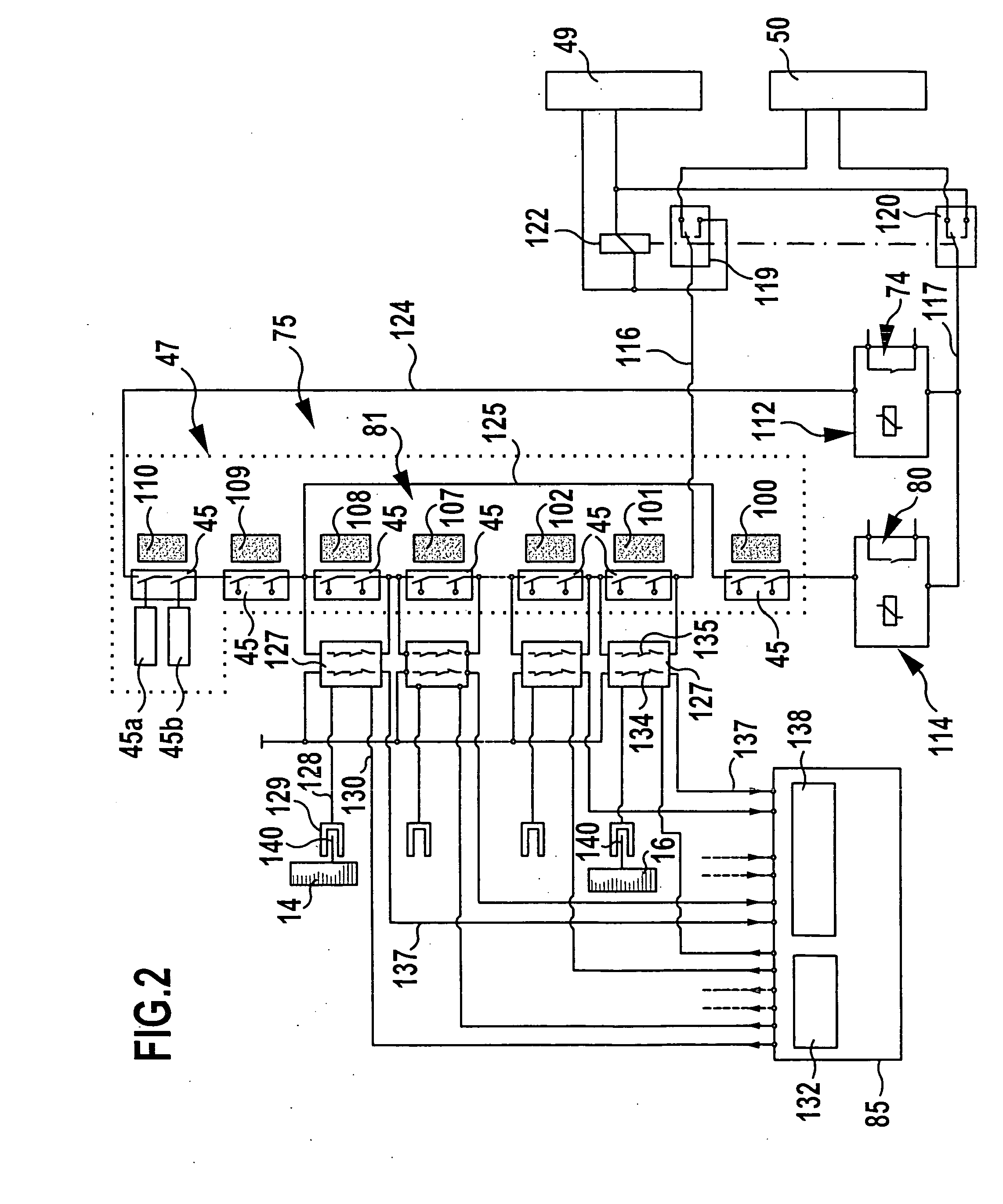
[0042] In FIGS. 1 and 2, an elevator installation according to the invention is represented in a greatly schematized form and designated overall by the reference numeral 10. It comprises two cars disposed one above the other in a shaft 12, specifically an upper car 14 and a lower car 16, which can be made to travel individually up and down along a common traveling path on guides 11, 13. To achieve a better overview, in the drawing the shaft 12 is shown offset in relation to the two cars 14 and 16.
[0043] The upper car 14 is coupled to a counterweight 19 via a suspension cable 18, and the lower car 16 is coupled to a counterweight 22 via a suspension cable 21. Each car 14 and 16 has a separate drive associated with it in the form of an electric drive motor 24 and 25, respectively, and in each case a separate brake 28 and 29, respectively. The drive motors 24 and 25 in each case drive a traction sheave 31 and 32, respectively, over which the suspension cables 18 and 21 are led.
[0044] ...
second embodiment
[0087] In FIG. 3, an elevator installation according to the invention is schematically represented and provided overall with the reference numeral 150. This is configured largely identically to the elevator installation 10 explained above with reference to FIGS. 1 and 2. Therefore, the same reference numerals as in FIGS. 1 and 2 are used for identical components in FIG. 3. To avoid repetition, reference is made in this respect to the full content of the statements made above.
[0088] In the case of the elevator installation 150 represented in FIG. 3, the upper car 14 has a proximity switch 152, the switching contacts 153 of which are integrated into the shaft monitoring circuit 72 of the safety chain 71 associated with the upper car 14, the switching contacts 153 being connected in series with further switching contacts, known per se, of the safety circuit 72.
[0089] The actuation of the proximity switch 152 takes place by means of a switching roller 154, which is mounted on the outsi...
PUM
 Abstract
Description
Claims
Application Information
 - R&D
- Intellectual Property
- Life Sciences
- Materials
- Tech Scout
- Unparalleled Data Quality
- Higher Quality Content
- 60% Fewer Hallucinations
Browse by: Latest US Patents, China's latest patents, Technical Efficacy Thesaurus, Application Domain, Technology Topic, Popular Technical Reports.
© 2025 PatSnap. All rights reserved.Legal|Privacy policy|Modern Slavery Act Transparency Statement|Sitemap|About US| Contact US: help@patsnap.com


