
Portable equipment for measuring and/or monitoring the heart rate

a heart rate and portability technology, applied in the field of portability equipment, can solve the problems of difficult removal of artifacts in such devices, and achieve the effect of reducing the vascularization of the heart rate and facilitating the removal of artefacts

Active Publication Date: 2007-02-13
CSEM CENT SUISSE DELECTRONIQUE & DE MICROTECHNIQUE SA RECH & DEV
View PDF11 Cites 112 Cited by
  • Summary
  • Abstract
  • Description
  • Claims
  • Application Information

AI Technical Summary

Benefits of technology

[0007]Because of the above features, the heart rate measuring function can be associated with that of a sound reproduction device, like for example a walkman. Sound reproduction devices of this kind are very widely used, especially by persons exercising a sporting activity. The information concerning the heart rate can therefore be provided as a complement to the reproduced sound signal, which is generally entertaining and that the wearer of the equipment is used to listening to. Also, the complementary information is presented by means of a sound reproduction component (an ear cushion) that is of the usual kind and is placed over the ear of the wearer of the equipment in the usual way, the exterior shape of the probe placed over the ear being intentionally no different from that of a standard ear cushion. Furthermore, the heart rate measurement function is implemented very discreetly, which users of the equipment may see as an advantage. It will finally be noted that an ear cushion is held in place without problems despite the movements of the wearer, while the connection between the ear cushion and the body of the walkman is not modified either (at least externally), and requires only a connecting cable slightly modified compared to the usual cable. It can therefore be very robust.
[0008]In addition prior art portable devices which are in the form of an ear clip, besides the fact they pinch the ear lobe and therefore hinder its vascularization, are fixed on a flexible part of the ear (the ear lobe) and it is therefore difficult to remove in such devices the artifacts due to the motion of the body of the wearer. According to the present invention, the detecting unit being incorporated in an ear cushion, it is advantageously adapted to be worn in contact with a stiff part of the ear (the cartilage) and therefore it becomes easier to remove the artefacts due to the motion of the body.

Problems solved by technology

In addition prior art portable devices which are in the form of an ear clip, besides the fact they pinch the ear lobe and therefore hinder its vascularization, are fixed on a flexible part of the ear (the ear lobe) and it is therefore difficult to remove in such devices the artifacts due to the motion of the body of the wearer.

Method used


Image

  • Portable equipment for measuring and/or monitoring the heart rate
  • Portable equipment for measuring and/or monitoring the heart rate
  • Portable equipment for measuring and/or monitoring the heart rate

Examples


Embodiment Construction

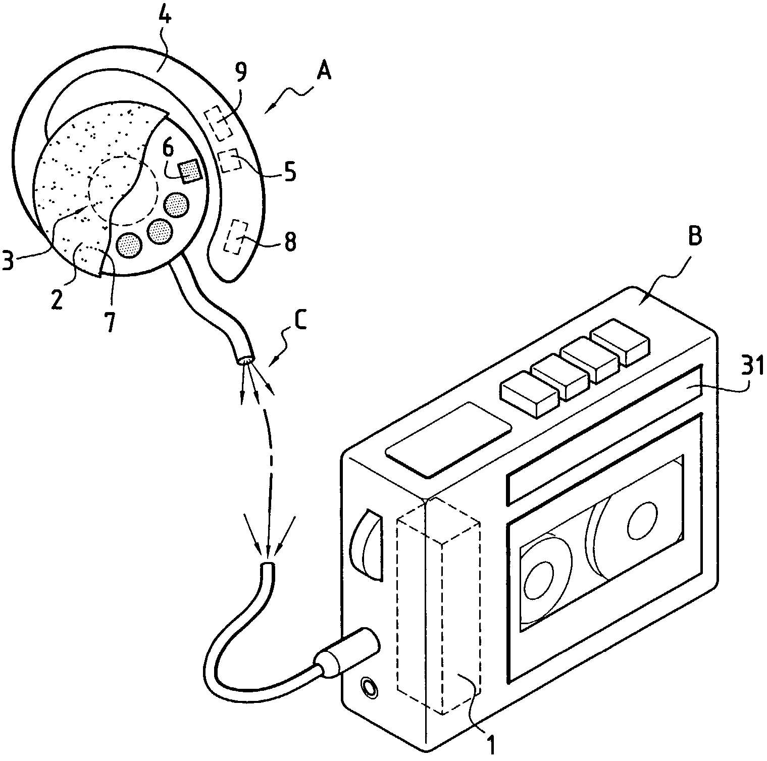
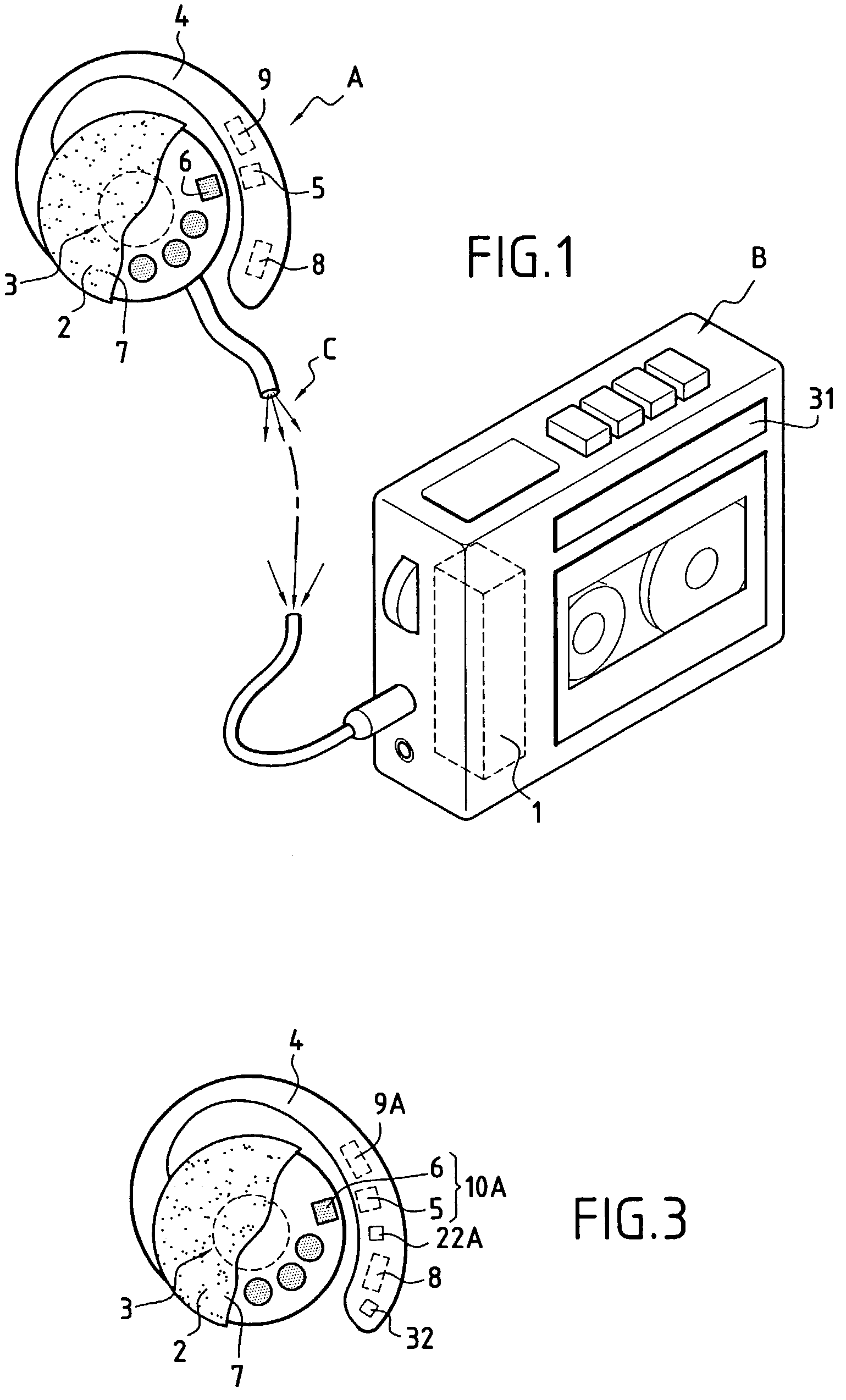
[0023]FIG. 1 shows a first embodiment of portable equipment according to the invention.

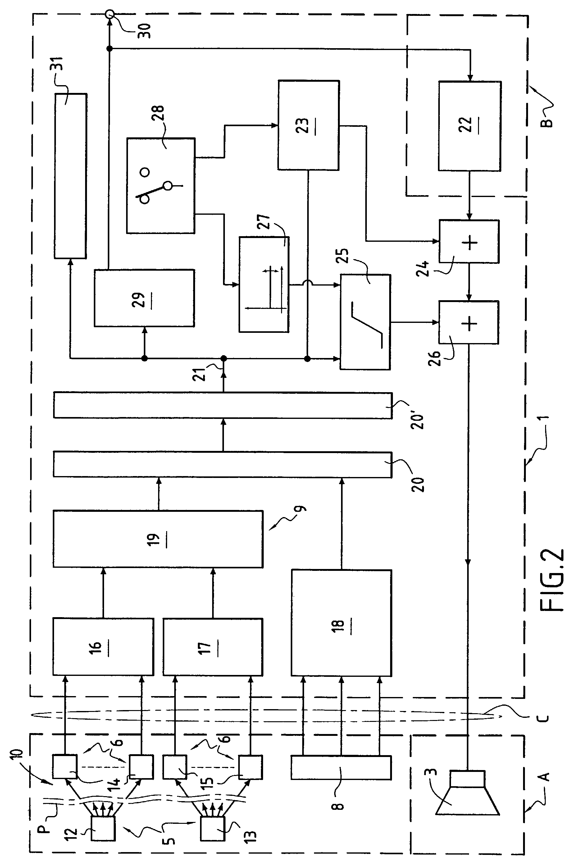
[0024]The equipment comprises a first unit A adapted in particular to measure the heart rate and a second sound reproduction unit B adapted in particular to reproduce sound, the two units being interconnected by a cable C. In the embodiment shown, the unit B is an audiocassette player, preferably adapted to be easily worn by a user, as is usual for the devices usually known as “walkmans”. Of course, the invention applies to other sound reproduction devices using other recording media, such as compact disks (CD), digital versatile disks (DVD), etc. The cassette player B is of standard design and is therefore not described in detail. Suffice to say that its sound reproduction electrical circuit has added components that are schematically represented in FIG. 1 by a functional unit 1 that is described later.

[0025]The unit A takes the form of an ear cushion comprising a generally circular casing 2 adap...


PUM


Abstract

Portable equipment including in combination a heart rate measuring device and a sound reproduction unit including means for supplying a signal representative of the sound reproduction and for supplying sound information to a sound transducer, wherein said measuring device and said sound transducer are mounted at least in part in an assembly adapted to be fixed to an ear of a wearer of the equipment and, wherein said sound reproduction unit includes means for optionally substituting for and / or superimposing on said signal representative of said sound reproduction a signal generated from signals from said measuring device and representative of said heart rate. The equipment can take the form of a walkman, for example, or a hearing aid for the hard of hearing.

Description

FIELD OF THE INVENTION[0001]The present invention relates to portable equipment for optically measuring and / or monitoring the heart rate.BACKGROUND OF THE INVENTION[0002]Many variants of this type of equipment exist already. They include an optical probe designed to be placed on a region of the skin of a user. The probe includes an emitter for radiating light into the tissue of that region and a receiver for picking up energy coming from the tissue (for example as a result of reflection on the tissue or transmission through the tissue) whose optical characteristics vary in dependence upon the circulation of the blood. The signal supplied by the receiver is analyzed and artifacts caused in particular by the movements of the user, ambient light, etc. are removed in an electronic processing unit whose output signal can be made perceptible in any appropriate manner, for example by displaying it on a screen, by reproducing it audibly, etc. The output signal can be compared to a threshold...

Claims


Application Information

Patent Timeline
Patent Type & Authority Patents(United States)
IPC IPC(8): A61B5/02A61B5/024A61B5/0245A61B5/11
CPCA61B5/02438A61B5/721A61B5/6815A61B5/02455A61B5/11
Inventor VERJUS, CHRISTOPHEVETTER, ROLFCELKA, PATRICKRENEVEY, PHILIPPE
Owner CSEM CENT SUISSE DELECTRONIQUE & DE MICROTECHNIQUE SA RECH & DEV
Learn More