
Implant arrangement and device

a technology for implants and parts, applied in the field of arrangement of implants and attachment parts, can solve the problems of compromising cement, difficulty in adjusting and adjusting, and difficulty in adjusting the amount of cement or equivalent, and achieves the effects of reducing the difficulty of adjusting and adjusting

Inactive Publication Date: 2007-02-13
NOBEL BIOCARE SERVICES AG
View PDF11 Cites 75 Cited by
  • Summary
  • Abstract
  • Description
  • Claims
  • Application Information

AI Technical Summary

Benefits of technology

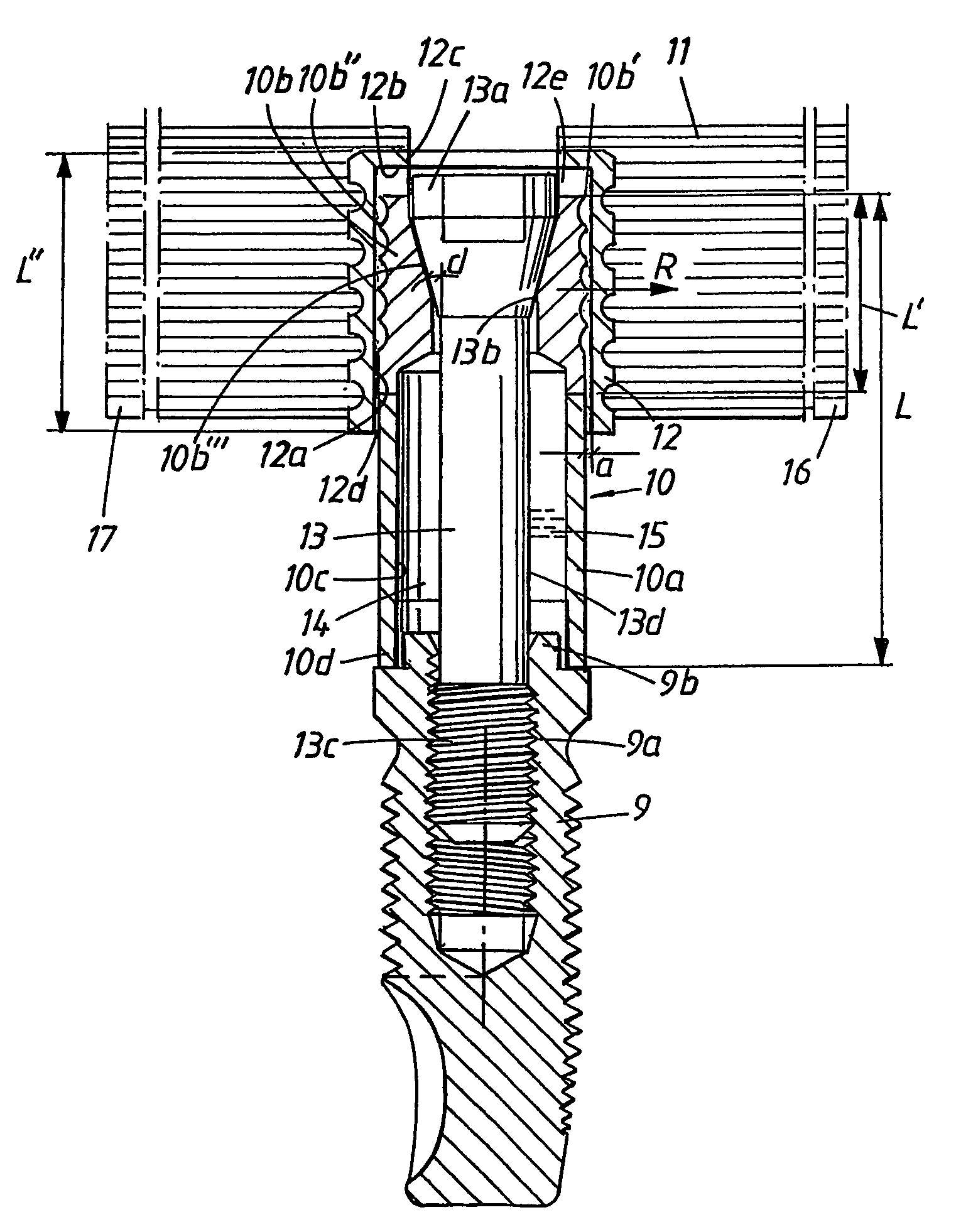
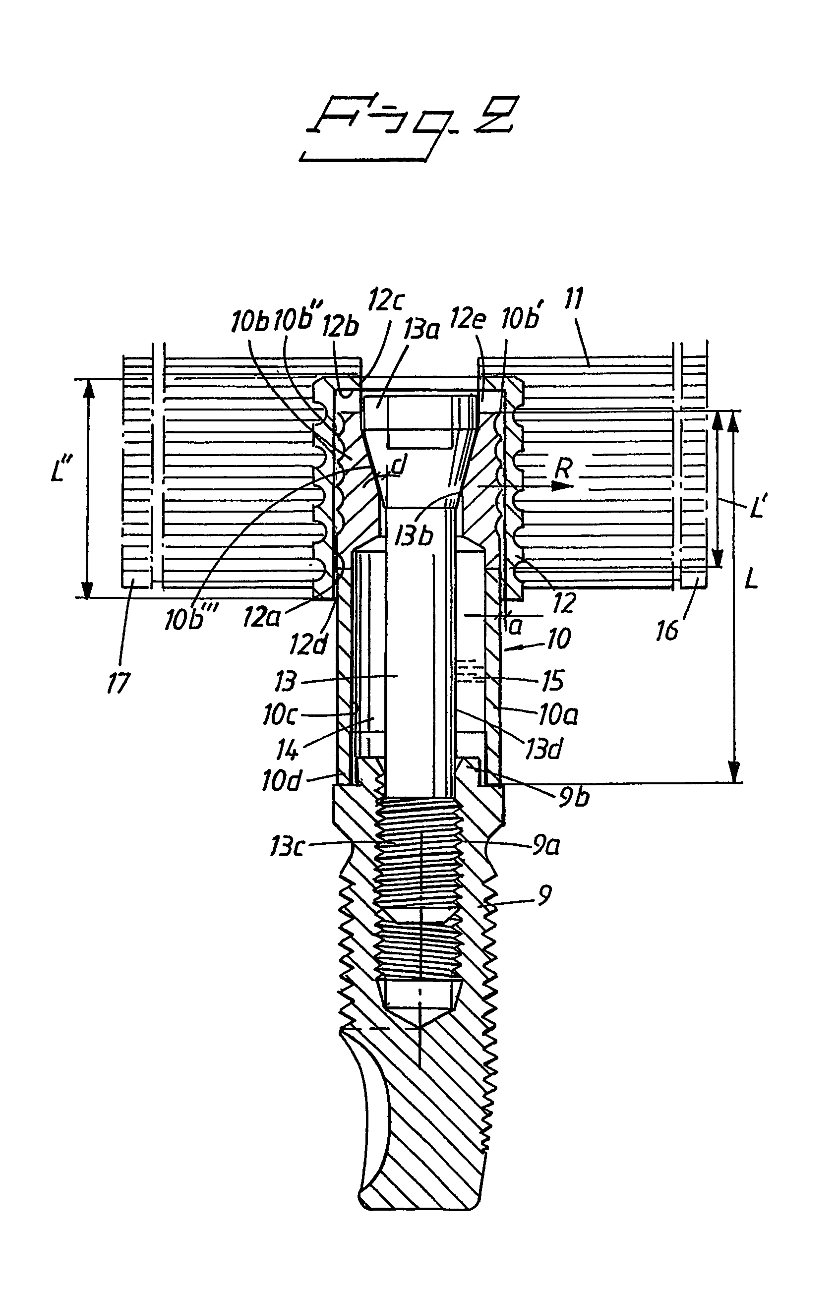
[0010]By means of what is proposed above, a patient-friendly securing principle for dental bridges in implants is obtained which is rapid and effective and, inter alia, permits easy readjustment and exchange of the respective attachment part / dental bridge. Material types which have proven themselves in this context can be used in the bridge and spacer sleeve constructions and in the fastening screws. The application function is considerably simplified and can for example be controlled by end-position indication or end-position stops in one of the bridge's recesses. When the end position has been reached, the bridge is screwed tightly in place and at the same time acquires its “horizontal position” in the patient's mouth. Other longitudnal displacement positions between recesses and portions on other implants are determined by the initial fitting, and anchoring or anchorings can also be carried out in these longitudinal displacement positions.

Problems solved by technology

The disadvantage of using cement or cement-like agents is considerable.
Thus, for example, problems may arise in using the right amount of cement or equivalent.
Too little cement may compromise the result, and too much cement means that excess cement occurs at the implant site.
Problems may also arise relating to the hardening of the cement.
It is also difficult, during the hardening process, to achieve exact and permanent positions for the respective bridge.
Various types of cement (for example acryl-containing cement) are considered difficult to handle from the point of view of soiling.
If there is no time to apply the dental bridge to the implants before the cement has hardened, it may also be difficult to make readjustments of the bridge position, since the cement connection then has to be broken up.
Contamination may also arise on the jaw bone and gingiva (gum) when working with cement.

Method used


Image

  • Implant arrangement and device
  • Implant arrangement and device
  • Implant arrangement and device

Examples


Embodiment Construction

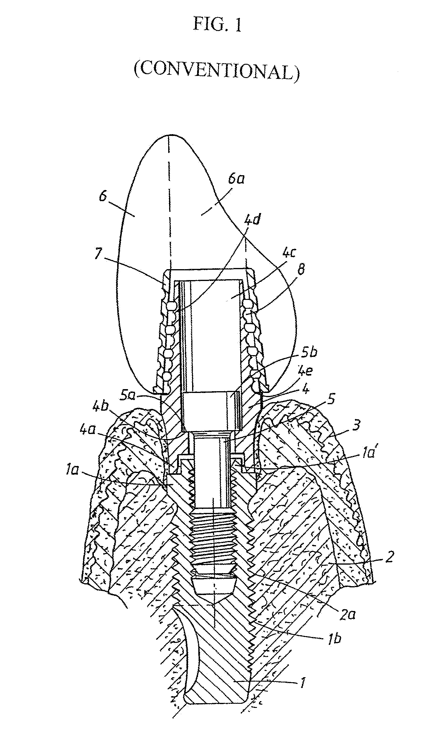
[0016]In FIG. 1, an implant is indicated by 1. The implant is screwed tightly in a jaw bone 2. The application of the implant can alternatively take place in another type of bone in the human body. The gum parts (gingiva) 3 of the jaw bone or equivalent have been exposed or opened at the implant site and have been shown in the folded back position. At its upper parts 1a, the implant can cooperate with or is provided with a spacer sleeve 4 which is anchored to the upper parts of the implant at an upwardly projecting flange or hexagon 1a′ on the implant. The spacer sleeve has at the bottom a circular part 4a which surrounds the upwardly projecting part 1a′. In a manner known per se, the sleeve is also provided with an internal flange 4b which constitutes a support for a fastening screw, whose bottom surface 5a can cooperate with the internal flange in order to permit anchoring of the spacer sleeve in the implant by means of the fastening screw 5. The spacer sleeve is provided with an ...


PUM


Abstract

In an arrangement with implant and attachment part / dental bridge, the latter comprises one or more recessed walls. The implant is designed or can cooperate with a portion which can be arranged on a spacer sleeve belonging to the implant and extends substantially parallel to the recessed wall. The attachment part and its respective recessed wall is arranged with displaceability in the main longitudinal direction of the implant relative to the outer surface of the portion. The portion is arranged to be expandable so that, in a given position of longitudinal displacement, it is possible to achieve interaction between outer surfaces of the portion and the recessed wall and thus anchoring of the attachment part to the portion or the implant. The invention also relates to a device with two or more implants and dental bridge. By means of the invention, discrepancies between dental bridge and the implants can be taken up in an effective and rapid securing principle.

Description

BACKGROUND OF THE INVENTION[0001]The present invention relates to an arrangement with implant and attachment part, for example in the form of a dental bridge. The attachment part comprises a recessed wall and the implant is designed or can cooperate with a portion which preferably can be applied on a spacer sleeve belonging to the implant. Said portion preferably extends substantially parallel to the recessed wall.[0002]The invention also relates to a device with two or more implants and an attachment part which can cooperate with these and which in accordance with the above can have the form of a bridge. The attachment part comprises recesses for application to the implants via portions arranged on or applied to these and intended to extend into the recesses.[0003]In production by means of modeling of bridges or the like for implants in jaw bone, there is always play between the concrete installation situation and the product finally produced, for example the bridge. The principle ...

Claims


Application Information

Patent Timeline
IPC IPC(8): A61C8/00
CPCA61C8/0048
Inventor BRAJNOVIC, IZIDOR
Owner NOBEL BIOCARE SERVICES AG
Learn More