
Integrated labyrinth and carbon seal

a technology of carbon seals and labyrinths, applied in the field of shaft seals, can solve the problems of less effective at maintaining a small gap between the shafts, and achieve the effect of improving the shaft seal

Active Publication Date: 2007-02-13
PRATT & WHITNEY CANADA CORP
View PDF17 Cites 50 Cited by
  • Summary
  • Abstract
  • Description
  • Claims
  • Application Information

AI Technical Summary

Benefits of technology

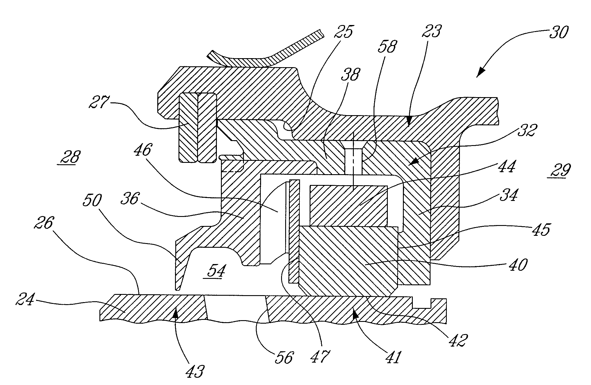
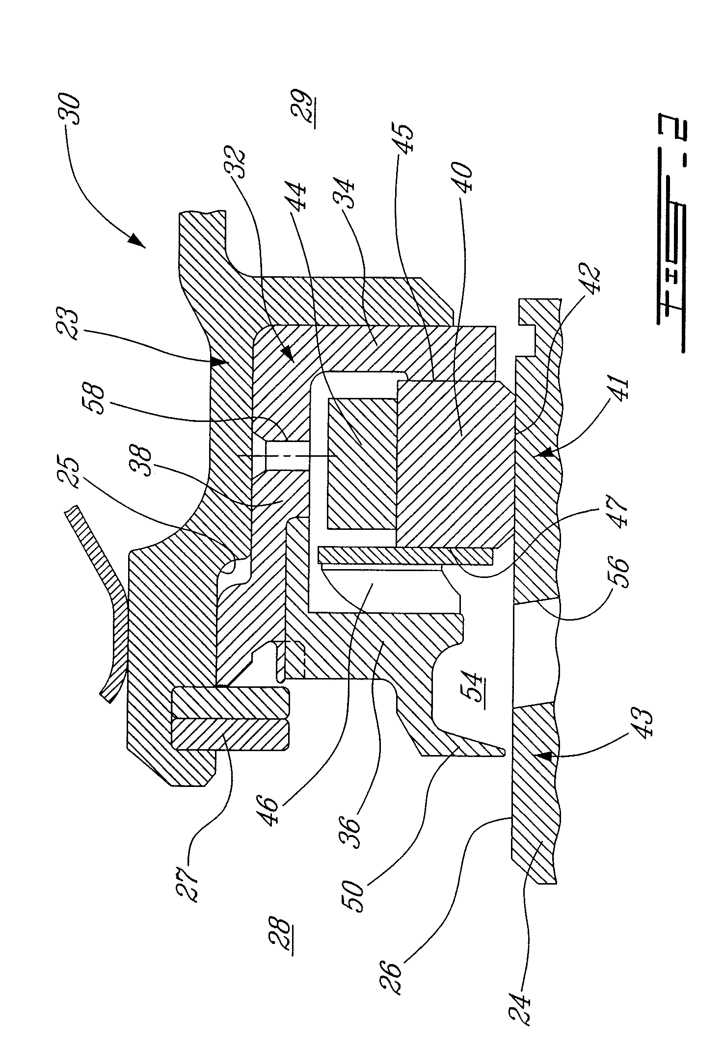
The present invention provides an improved shaft seal for gas turbine engines. The invention includes an integrated double seal assembly that includes a carbon seal ring and a labyrinth seal, which work together to seal the rotating shaft. The seal assembly is supported by a static outer housing and includes a shrink band to maintain the carbon seal in compression. The labyrinth seal has at least one annular labyrinth fin that rotates with the shaft and provides a seal with the outer shaft surface. The invention also includes a gas turbine engine comprising a compressor, combustor, and turbine, where the double seal assembly provides fluid sealing between the engine cavities. The technical effects of the invention include improved sealing efficiency, reduced leakage, and improved performance of gas turbine engines.

Problems solved by technology

However, labyrinth seals are more affected by shaft eccentricities and thermal expansion, and therefore are less effective at maintaining a small gap between the shaft and the seal structure.

Method used


Image

  • Integrated labyrinth and carbon seal
  • Integrated labyrinth and carbon seal
  • Integrated labyrinth and carbon seal

Examples


Embodiment Construction

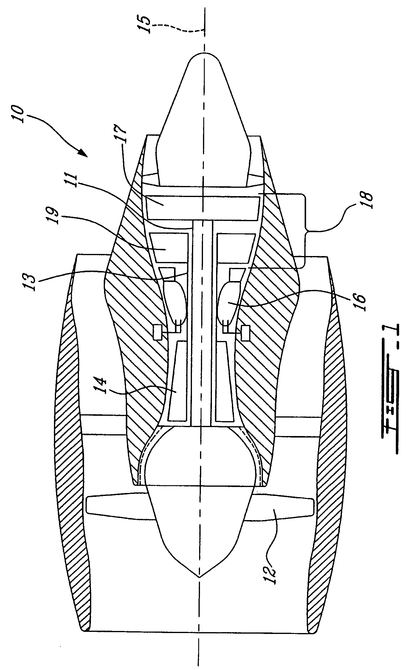
[0014]FIG. 1 illustrates a gas turbine engine 10 of a type preferably provided for use in subsonic flight, generally comprising in serial flow communication a fan 12 through which ambient air is propelled, a multistage compressor 14 for pressurizing the air, a combustor 16 in which the compressed air is mixed with fuel and ignited for generating an annular stream of hot combustion gases, and a turbine section 18 for extracting energy from the combustion gases.

[0015]The turbine section 18 comprises a low pressure turbine 17 and a high pressure turbine 19. The engine 10 also preferably includes at least two rotatable main engine shafts, namely a first inner shaft 11 interconnecting the fan 12 with the low pressure turbine 17, and a second outer shaft 13 interconnecting the compressor 14 with the high pressure turbine 19. The inner and outer main engine shafts 11 and 13 are concentric and rotate about the centerline axis 15 which is preferably collinear with their longitudinal axes.

[00...


PUM


Abstract

An integrated double seal assembly includes a carbon seal ring and at least one annular labyrinth seal fin. The seal provides a compact solution for sealing a rotating shaft.

Description

TECHNICAL FIELD[0001]The invention relates generally to seals for rotating elements and, more particularly, to an improved shaft seal for use in a gas turbine engine.BACKGROUND OF THE ART[0002]Controlled gap carbon seals and multiple-tooth labyrinth seals are but two distinct and independent seals which exist and which are used to provide fluid seals around rotating shafts, particularly those in high temperature environments such as in gas turbine engines. In certain applications, double seals are employed, in which two seals, such as a double carbon seal for example, are disposed side-by-side.[0003]Controlled gap carbon seals provide relatively good sealing capabilities due to the relatively small clearances which can be maintained between the carbon ring seal and an inner runner, such as a rotating shaft of a gas turbine engine for example. Such tight shaft clearances are possible due to the ability of the carbon ring seal to radially “float” relatively to the rotating shaft, whic...

Claims


Application Information

Patent Timeline
Patent Type & Authority Patents(United States)
IPC IPC(8): F01D11/02F03B11/00
CPCF01D11/003F16J15/441F01D11/02
Inventor LABBE, MICHELGEKHT, EUGENE
Owner PRATT & WHITNEY CANADA CORP
Learn More