
Method of using a kingpin lock holder

a technology of kingpin lock and holder, which is applied in the field of holding devices, can solve the problems of kingpin locks that are not easy to be removed by cutting tools, kingpin locks have major problems, and kingpins are immediately greasy when first engaged, and achieve the effects of convenient inserting into either lock device, light weight of the holder, and ease of us

Inactive Publication Date: 2007-02-13
ESCALANTE III JUAN NEPOMUSENO
View PDF7 Cites 6 Cited by
  • Summary
  • Abstract
  • Description
  • Claims
  • Application Information

AI Technical Summary

Benefits of technology

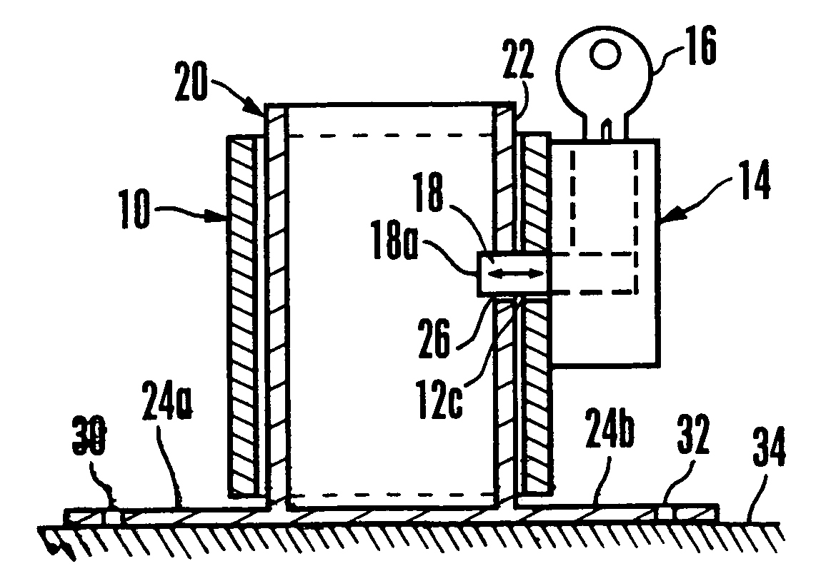
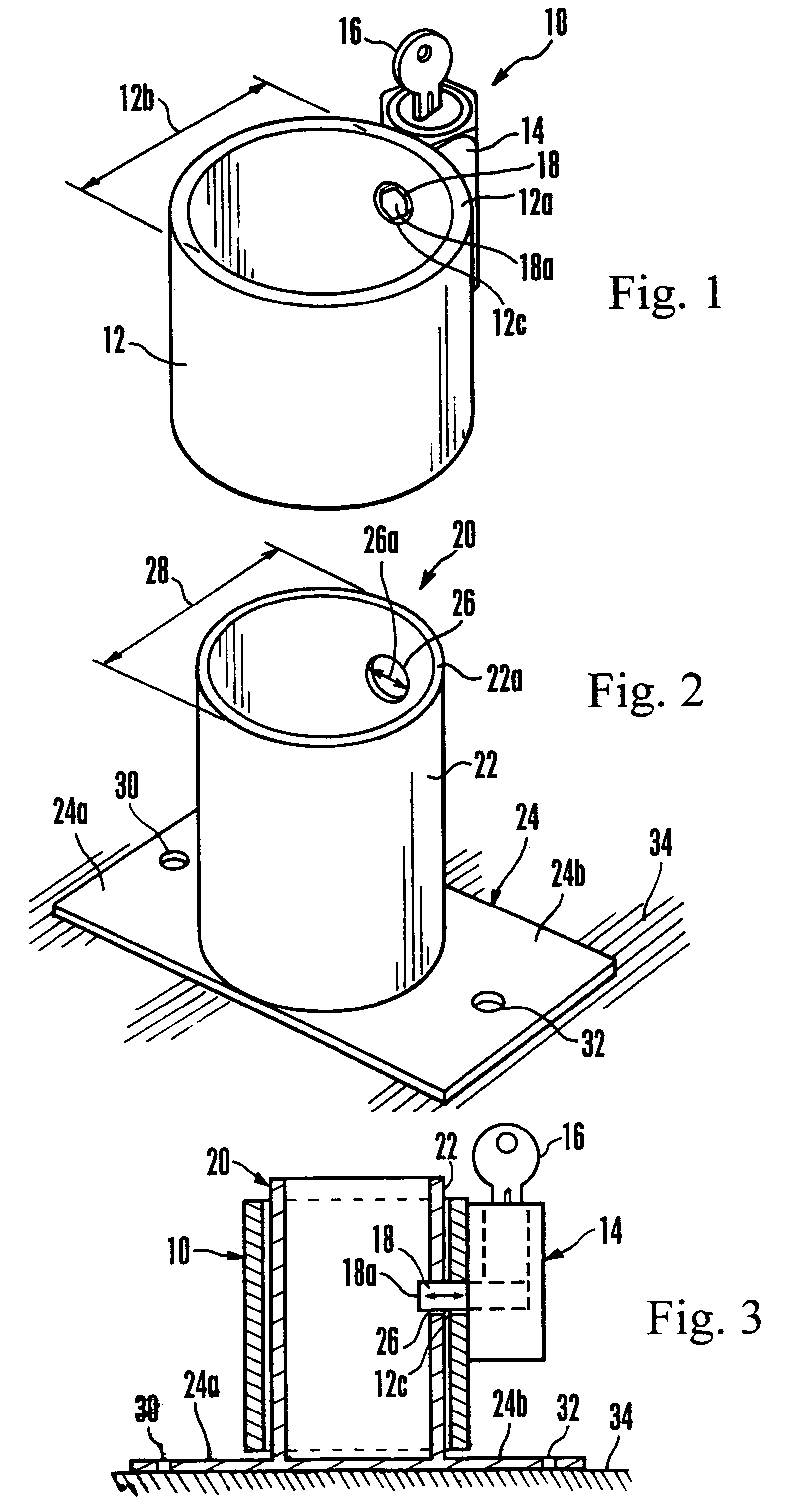
[0010]The above-mentioned difficulties and problems are overcome by the present invention. The present invention is an elegantly simple method of using the device. Applicant's Kingpin Lock Holder is a one piece, durable, cylinder-like device that is inserted within the main cylinder part of a kingpin lock. One preferred embodiment is used with the two primary kingpin lock devices previously described. The holder has an outside diameter in close tolerance to the inside diameter of either lock device. In addition, the holder is easily insertable into either lock device. A round hole is located within the wall of the holder such that a recess in the cylinder wall of each lock device aligns with the round hole in the holder. The diameter of the hole in the holder is sufficient to allow the metal tongue to be inserted from the lock device through the hole in the holder. Then the key in the kingpin lock device is removed leaving the kingpin lock secured to the holder. In addition, the kingpin lock holder has a metal plate perpendicularly welded to the cylinder part. The plate has, preferably, a hole that has been drilled through each flange of the plate. Then bolts are used to secure the holder to another metal surface. The holder can also be welded to secure it to another metal surface. The surface could be the underside of a trailer or box near the kingpin. This location permits the kingpin lock to be proximate to the kingpin for convenience in installing the lock. Another location could be in a storage compartment behind the cab of the tractor.
[0011]Key novel features or advantages include the ease of use, the light weight of the holder, its flexibility in location on a trailer or tractor, its inexpensive nature to manufacture, and flexibility in design to accommodate other larger kingpin lock devices. In addition, major advantages include preventing the need for holding the greasy kingpin lock and ease of finding the lock. These, and other, novel features and advantages of the present invention are set forth more completely in the accompanying drawings and the following description.

Problems solved by technology

The reason the kingpin lock cannot be removed from the kingpin is 1) because the key is necessary for locking and unlocking the lock, 2) the metal tongue cannot be slipped off the kingpin since the kingpin upper and lower diameters are greater than the center diameter where the metal tongue is in contact, and 3) because the metal cylindrical walls of the kingpin locks are thick enough to make removable by a cutting torch highly impractical and time consuming.
Unfortunately, the kingpin locks have some major disadvantages.
Because the slot on the tractor is heavily greased, the kingpin immediately becomes greasy when first engaged.
Then the kingpin lock becomes greasy almost immediately upon use.
However, limited space exists to store enough rags to be constantly wiping off the lock.
The driver now is reluctant to use the pinlock because it is absolutely filthy, has been thrown in a box with other things, and cannot be easily cleaned because all the rags are just as greasy.
Herein lies the key problem.
Although the kingpin lock is required to be used to prevent theft, the drivers tend to not use it because of the inconvenience in looking for and using the pinlock.

Method used


Image

  • Method of using a kingpin lock holder
  • Method of using a kingpin lock holder

Examples


Embodiment Construction

[0016]The above-mentioned difficulties and problems of the prior art are overcome by the present invention. Referring first to FIG. 1, a perspective view of a representative kingpin lock device 10 is shown comprising a cylinder 12, a lock mechanism 14, and a key 16. The present invention holds lock device 10. However, a more complete description of the lock device 10 is necessary before describing the present invention.

[0017]The cylinder 12 is the primary structural feature of the lock device 10. Welded to the cylinder 12 is the lock mechanism 14. As shown in FIG. 1, the key 16 is inserted into the lock mechanism 14. More specifically, the cylinder 12 further comprises a cylinder wall 12a with a cylinder inside diameter 12b. In addition a cylinder wall recess 12c is shown. Within the wall recess 12c, a metal tongue 18 is seen. The metal tongue 18 is actuated by the key 16 when the lock device 10 is slipped over a kingpin (not shown) on a semi-trailer. The kingpin is the metal struct...


PUM


Abstract

The present invention is a method of using a durable, cylinder-like device that is inserted within the main cylinder part of a kingpin lock. One preferred embodiment, of several, has an outside diameter in close tolerance to the inside diameter of a kingpin lock device. In addition, the holder is easily insertable into the kingpin lock device. A round hole is located within the wall of the holder such that the hole in a cylinder wall of each kingpin lock device aligns with the hole in the holder. The diameter of the hole in the holder is sufficient to allow a metal tongue to be inserted from the kingpin lock device through the hole in the holder. Then a key in the lockpin device is removed leaving the lock device secured to the holder. In addition, the holder has a metal plate perpendicularly welded to the cylinder part. The surface could be the underside of a trailer or box or in a storage compartment behind the cab of a tractor.

Description

[0001]This application is a divisional application of KINGPIN LOCK HOLDER, application Ser. No. 10 / 845,329, dated May 14, 2004, abandoned by the same inventor and Applicant Juan Nepomuseno Escalante, claiming the benefit of said prior parent application under 35 U.S.C. 121 and filed under 37 CFR 1.53 (b).BACKGROUND OF THE INVENTION[0002]1. Field of the Invention[0003]The present invention relates generally to holding devices, and, more specifically, to a method of using a holder for a kingpin lock device. A kingpin is used in the trucking industry to join a tractor to a flatbed trailer or a box.[0004]2. Description of the Related Art[0005]The trucking industry moves the vast majority of all goods within the United States. The volume is staggering. More importantly, the value of these goods is billions of dollars every day. Therefore, some means of protection and security is needed to minimize losses due to theft of the trailers or boxes that are hauled using tractors. For example, o...

Claims


Application Information

Patent Timeline
Patent Type & Authority Patents(United States)
IPC IPC(8): B60R25/00F16B41/00B60D1/00B60D1/60E05B73/00
CPCB60D1/60Y10T70/40Y10T70/5027Y10T70/5867Y10T70/5982
Inventor ESCALANTE, III, JUAN NEPOMUSENO
Owner ESCALANTE III JUAN NEPOMUSENO
Learn More