
Plug-in connector for connecting two flat strip conductors and associated plug-in connector system

a plug-in connector and flat-strip technology, which is applied in the direction of connection, electrical apparatus, coupling device connection, etc., can solve the problems of complex junction region and high overall construction cos

Inactive Publication Date: 2007-02-06
FRAMATOME CONNECTORS INT SA
View PDF20 Cites 23 Cited by
  • Summary
  • Abstract
  • Description
  • Claims
  • Application Information

AI Technical Summary

Benefits of technology

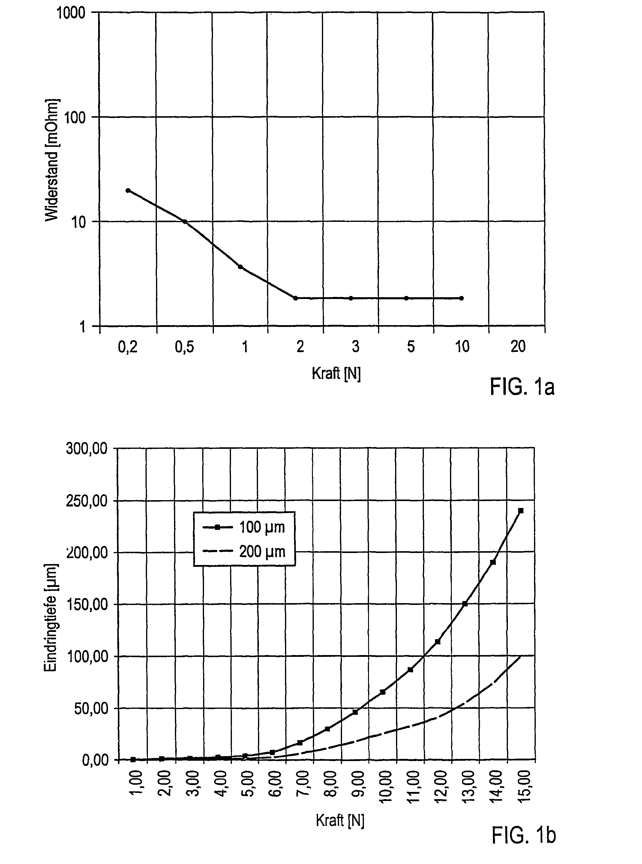
[0008]The object of the present invention is to create a connection between two ribbon conductors that fulfills the above requirements of normal contact force and that, at the same time, has a simple and cost-effective construction and makes possible a simple connection between the two conductors.

Problems solved by technology

This junction region is complicated and costly in terms of its overall construction with its shiftable holder, because an adjusting mechanism that can pivot and produces the requisite normal contact force is provided.

Method used


Image

  • Plug-in connector for connecting two flat strip conductors and associated plug-in connector system
  • Plug-in connector for connecting two flat strip conductors and associated plug-in connector system
  • Plug-in connector for connecting two flat strip conductors and associated plug-in connector system

Examples


Embodiment Construction

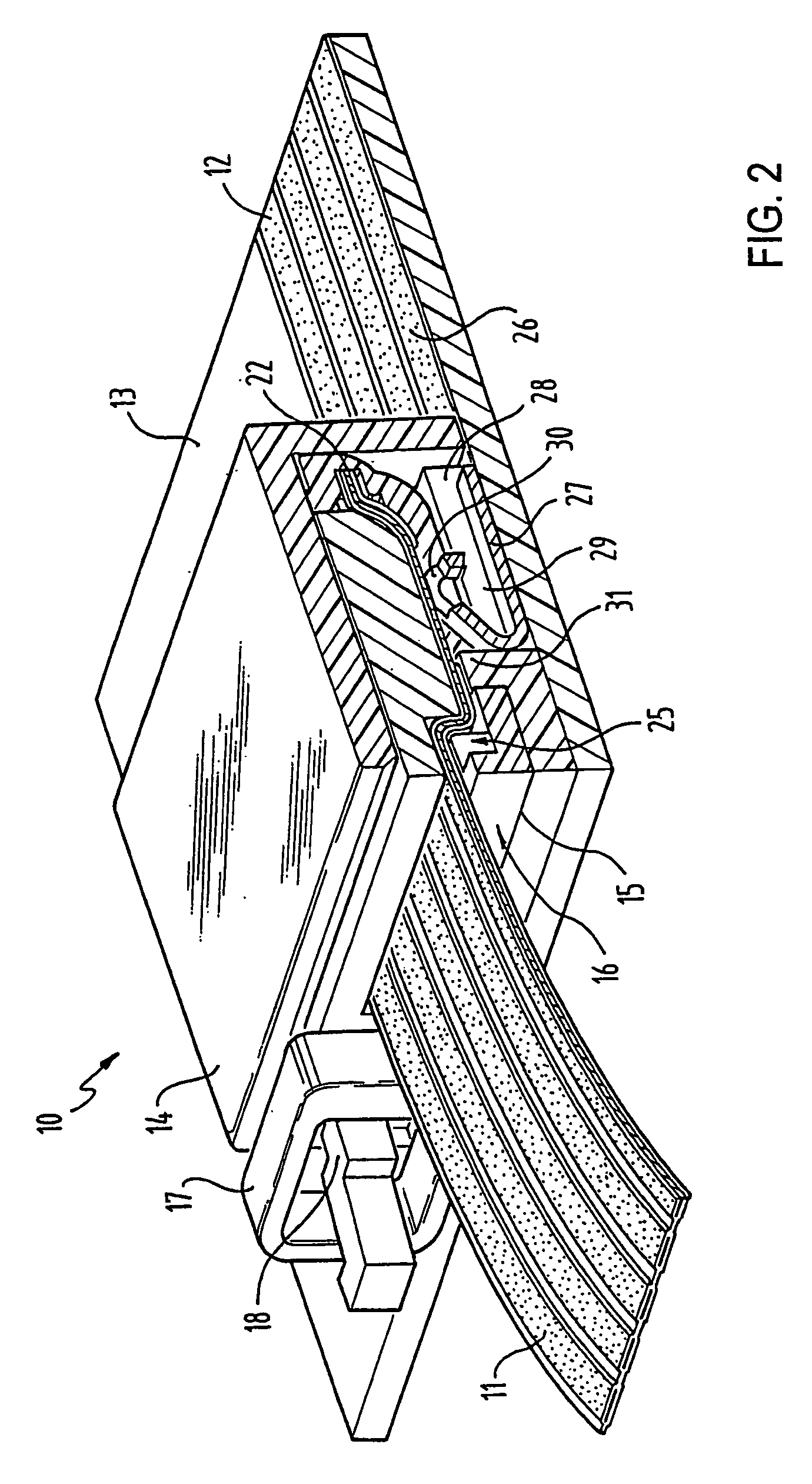
[0039]FIG. 2 shows a plug connector 10, which connects a first conductor 12 to a second conductor 11. The second conductor 11, in the present example, is a flexible ribbon conductor and the conductor 12, in the present example, is arranged on a circuit board 13. The second conductor 12 does not necessarily need to be arranged on a circuit board, but can also be arranged on any other support, which, in the present embodiment example, is preferably rigid. The plug connector 10 has a housing 14 with an opening 15, which forms an uptake for an inserted unit 16 (see FIGS. 3a and 3b), which can be attached by means of a catch 17 on the housing 14 of the plug connector 10. The inserted unit further has a coding 18 so that the inserted unit is not inserted into the housing from the wrong side.

[0040]As is evident in FIG. 3a, the inserted unit 16 has a housing 19 made of insulating material, on the top side of which a ribbed structure 20 is formed. The second ribbon conductor 11 is inserted w...


PUM


Abstract

The invention relates to a plug-in connector for connecting two flat strip conductors, including at least one spring element which provides the required normal contact power for the connection of the two flat strip conductors. The spring element contacts the two flat strip connectors and produces the electric contact between the two flat strip connectors.

Description

FIELD OF THE INVENTION [0001]The present invention relates to a plug connector for connecting two ribbon conductors as well as a plug connector system.BACKGROUND OF THE INVENTION [0002]Ribbon conductors are finding an ever broader field of application in many fields of technological use, because, with them, it is possible to construct, in a simple way, preformed wiring sets that can be installed simply and rapidly during assembly. One field of application of these ribbon conductors is increasingly the motor vehicle industry, because, owing to the use of many electronic components in vehicles, the resulting flows of current are becoming increasingly large. The larger conductor cross section required for a larger current flow can be accommodated in the case of ribbon conductors by the width of the conductive track.[0003]When two ribbon conductors are connected, among other things, spring elements are used, which are arranged in such a way that they afford the normal contact force betw...

Claims


Application Information

Patent Timeline
IPC IPC(8): H01R12/24H01RH01R3/00H01R12/61H01R12/62H01R12/78
CPCH01R12/78
Inventor PABST, THOMAS BERNHARDGELTSCH, HANS-OTTO
Owner FRAMATOME CONNECTORS INT SA
Learn More