
X-ray stand

a technology of x-ray and stand, which is applied in the field of x-ray stand, can solve the problems of large space and high cost of drive devices of this kind, and achieve the effect of low space and high positioning accuracy

Inactive Publication Date: 2007-01-30
SIEMENS HEALTHCARE GMBH
View PDF3 Cites 9 Cited by
  • Summary
  • Abstract
  • Description
  • Claims
  • Application Information

AI Technical Summary

Benefits of technology

This solution enables a cost-effective, space-efficient X-ray stand with high positioning accuracy and stable, vibration-free movement for large orbital displacements, suitable for multiple exposures during C arm travel.

Problems solved by technology

In connection with such large orbital displacements, it can be difficult with a drive device consisting of multiple motors to achieve a steady movement of the inner C arm and a desired positioning accuracy without a complicated control-engineering solution.
A drive device of this kind is therefore frequently expensive and needs a large amount of space.

Method used


Image

  • X-ray stand
  • X-ray stand
  • X-ray stand

Examples


Embodiment Construction

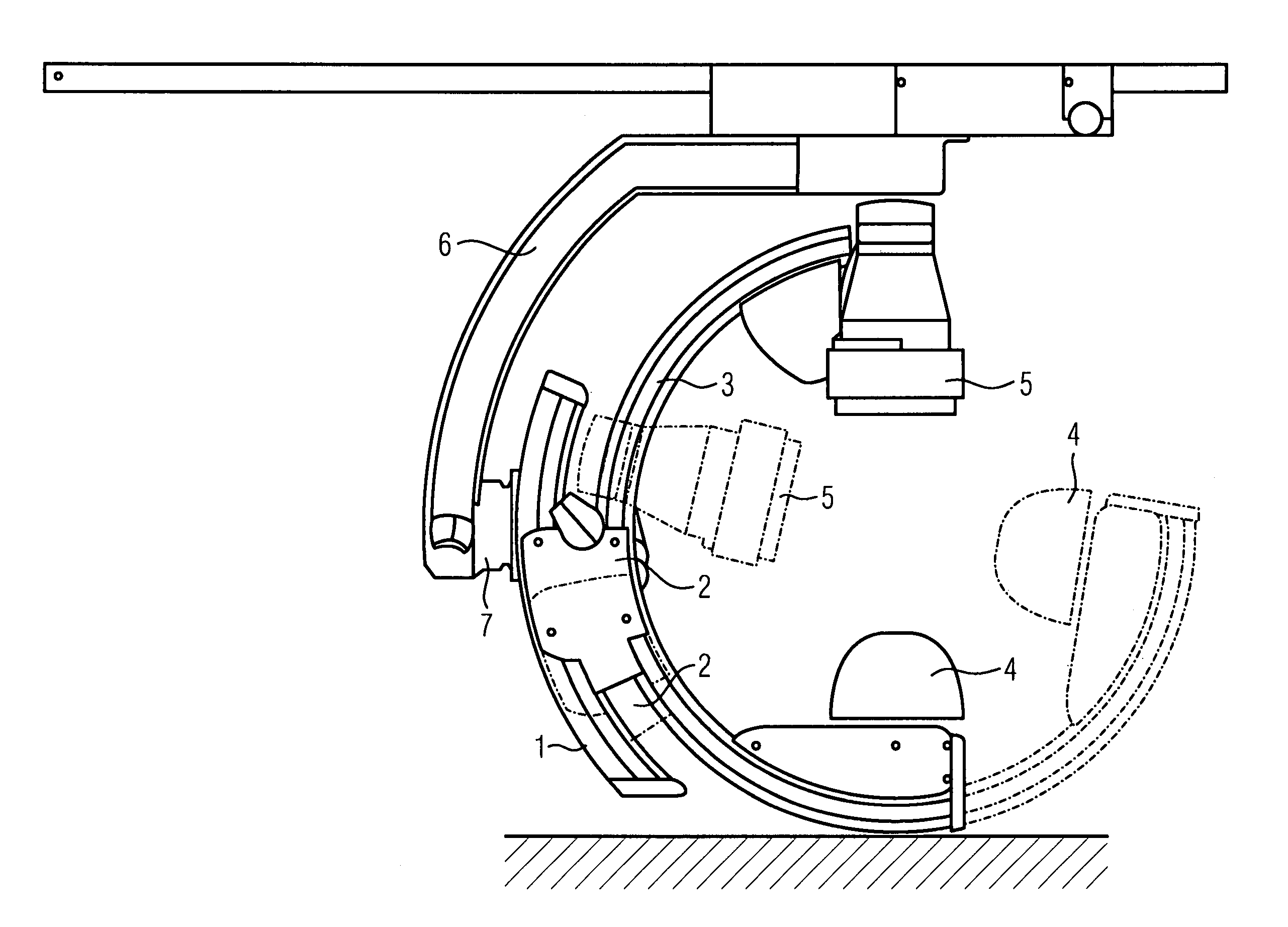
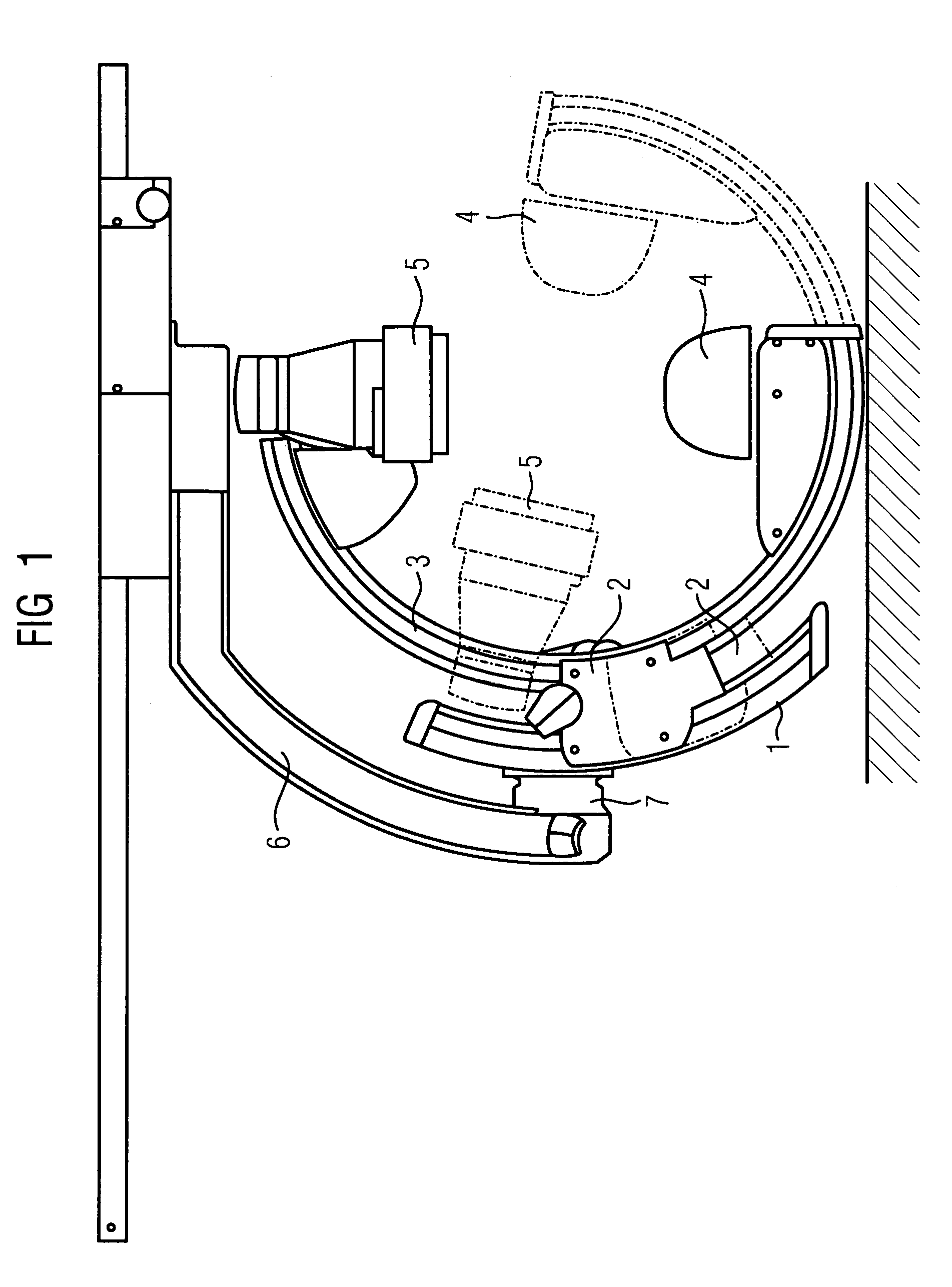
[0019]FIG. 1 shows an X-ray stand hung from the ceiling, said X-ray stand comprising an outer C arm 1 along which a support 2 for an inner C arm 3 is displaceably mounted. The inner C arm 3, which carries an X-ray tube 4 and an image intensifier 5, is displaceably arranged in the support 2. A drive device, which is not shown in the drawing and which will be described in more detail later, for the displacement of the support 2 along the outer C arm 1 and for the displacement of the inner C arm 3 along the support 2 is arranged in the support 2. The outer C arm 1 and thus also the support 2 and the inner C arm 3 are rotatably connected via a shaft 7 to a stand arm 6 of the stand.

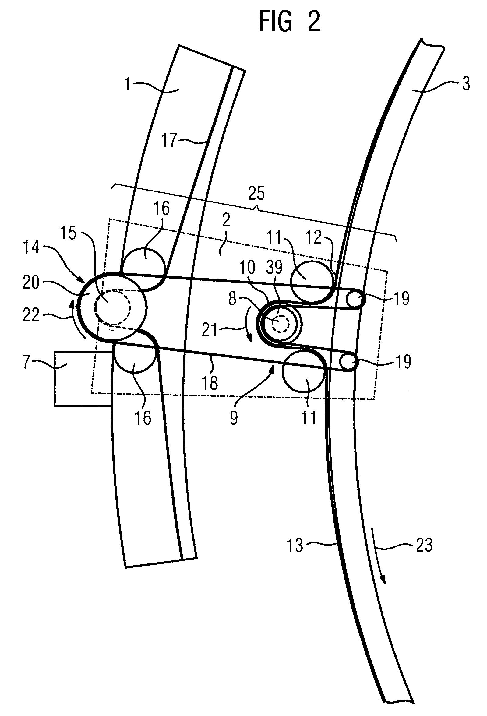
[0020]FIG. 2 shows in schematic form a drive device 25. The drive device 25 comprises a single drive means in the form of a motor 8 and a first omega-shaped belt transmission 9, consisting of a wheel 10 which is driven with the aid of the motor 8, of two guide rollers 11 which are mounted on each side of the w...


PUM


Abstract

The invention relates to an X-ray stand comprising an outer C arm along which a support for an inner C arm is displaceably mounted. The inner C arm which carries an X-ray tube and an image intensifier is displaceably arranged in the support. The X-ray stand further comprises a drive device for the displacement of the support along the outer C arm and the displacement of the inner C arm along the support. The aim of the invention is to create an X-ray stand of the above-described kind that comprises a drive device that is relatively inexpensive, requires little space and allows for a relatively high positioning accuracy. This aim is achieved in that the drive device is provided with a single drive means that influences the inner C arm and the support simultaneously in such a manner that the inner C arm and the support move in the same direction.

Description

CROSS REFERENCE TO RELATED APPLICATIONS[0001]This application claims priority to the Swedish application No. 0203517-8, filed Nov. 28, 2002 and to the International Application No. PCT / EP03 / 12156, filed Oct. 31, 2003 which are incorporated by reference herein in their entirety.FIELD OF INVENTION[0002]The invention relates to an X-ray stand comprising an outer C arm along which a support for an inner C arm is displaceably mounted, the inner C arm, which carries an X-ray tube and an image intensifier, being displaceably arranged in the support, and a drive device for the displacement of the support along the outer C arm and for the displacement of the inner C arm along the support.BACKGROUND OF INVENTION[0003]An X-ray stand of the aforementioned type is shown and described in U.S. Pat. No. 5,410,584. The drive device of this X-ray stand comprises two motors, the one motor being provided in order to displace the support along the outer C arm and the other motor being provided in order ...

Claims


Application Information

Patent Timeline
Patent Type & Authority Patents(United States)
IPC IPC(8): H05G1/02A61B6/00
CPCA61B6/4464A61B6/4441
Inventor ENGSTROM, GORANLUNDBERG, MIKAELMELLSTROM, ERIK
Owner SIEMENS HEALTHCARE GMBH
Learn More