
Piezoelectric structures

a piezoelectric structure and piezoelectric technology, applied in piezoelectric/electrostrictive/magnetostrictive devices, piezoelectric/electrostriction/magnetostriction machines, electrical equipment, etc., can solve the problem of not being able to achieve the relatively large amount of shape-change movement achieved by a single layer device, and not being as easy to make and use as might be desired

Inactive Publication Date: 2007-01-23
View PDF11 Cites 38 Cited by
  • Summary
  • Abstract
  • Description
  • Claims
  • Application Information

AI Technical Summary

Benefits of technology

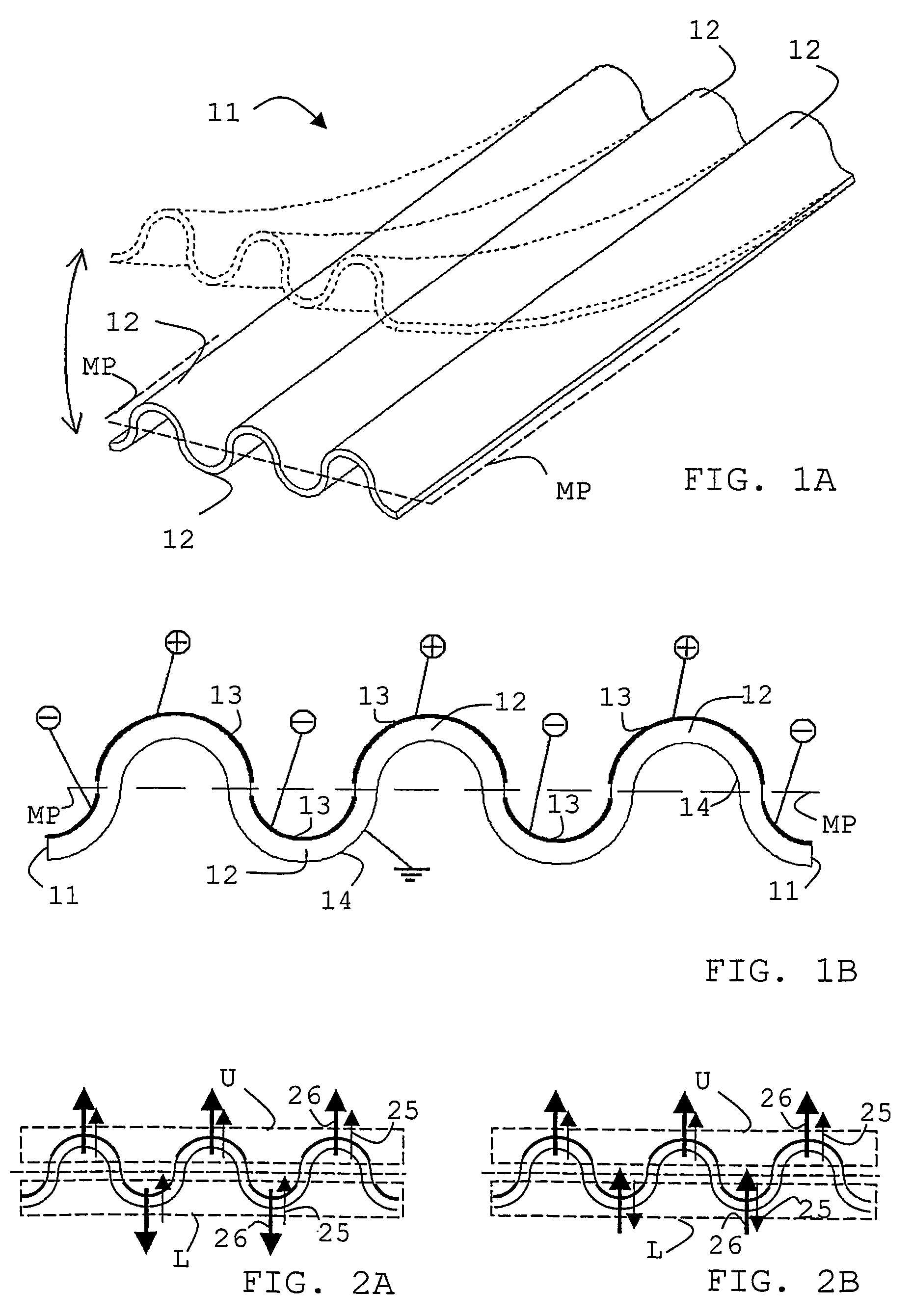
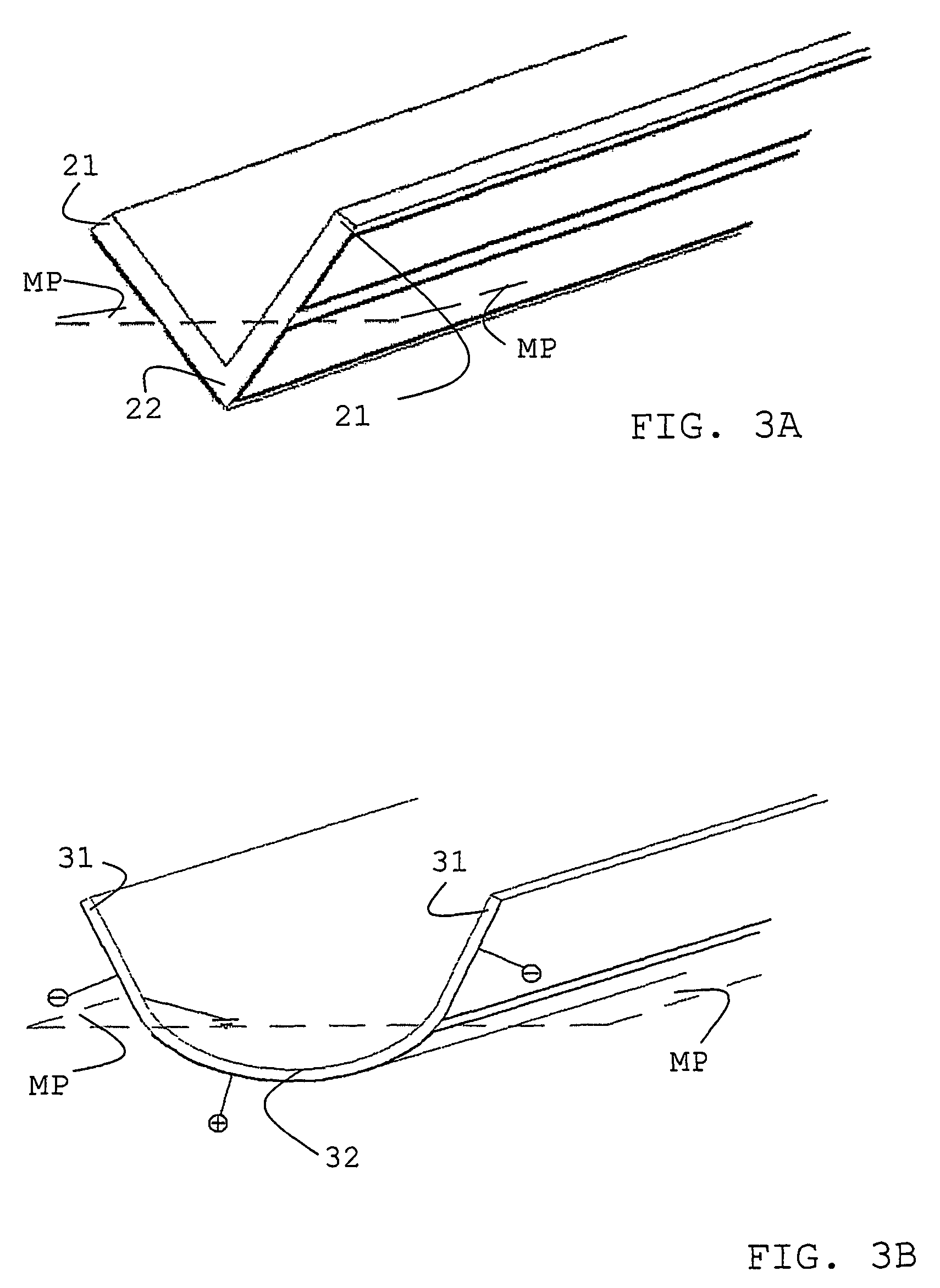
[0010]In one aspect, therefore, the invention provides a piezoelectric device the body of which is a simple, single layer of piezoelectric material physically shaped so as to have a multiplicity of seperate, distinct piezoelectric portions disposed in two generally planar groups that extend along, one on each side of, a nominal median plane through the whole body, which groups are thus spatially separated by and face each other across that median plane, with the result that any piezoelectric portion dimension change in the group on one side of the median plane will tend to bend the device normal to the median plane in the opposite direction to the same-sense piezoelectric portion dimension change in the group on the other side of that median plane.

Problems solved by technology

Benders, especially bimorph benders, work well in many situations, but because of the need to have, and connect to, their central electrode they are not as easy to make and use as might be desired.
Unfortunately, it has hitherto not been possible to achieve with a single layer device the relatively large amounts of shape-change movement attainable using the bending ability of a bimorph or even a unimorph.

Method used


Image

  • Piezoelectric structures
  • Piezoelectric structures
  • Piezoelectric structures

Examples


Embodiment Construction

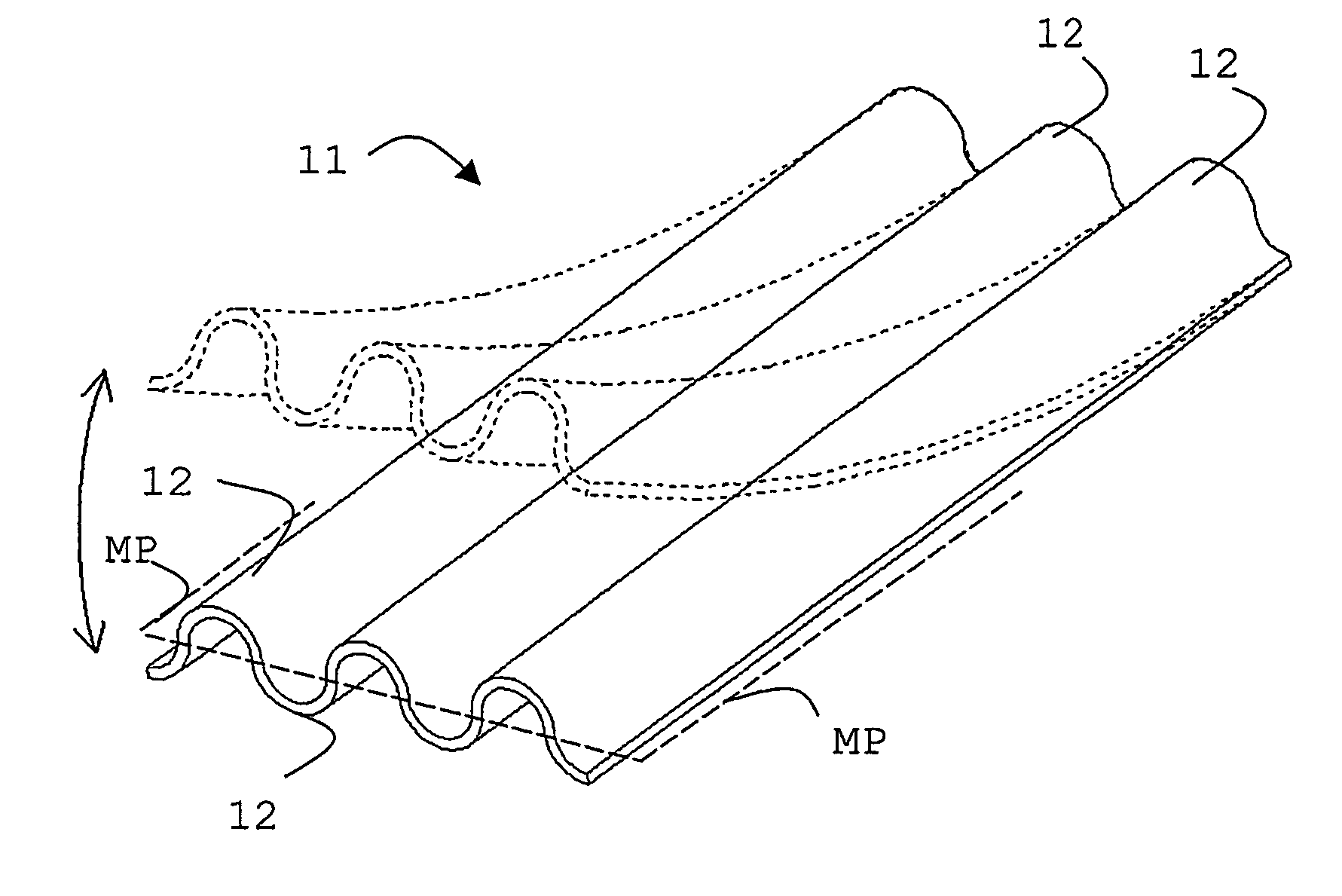
[0046]FIG. 1A shows in perspective a single-layer corrugated piezoelectric device of the invention; it shows how a straight bender can be made from merely a single layer of piezoelectric material and the appropriate electrodes.

[0047]The device is little more than an elongate sheet 11 of piezoelectric material that has been pressed (or folded) into a simple corrugated shape with the semi-circular corrugations 12 running the length of the sheet. The sheet has a notional median plane MP shown dashed, and has seven clearly distinct piezoelectric portions, three on one side (the upper half, as shown) and four on the other (the lower half). The upper three belong to one group that is generally planar, and the lower four belong to the other group. These groups are shown in dashed boxes U and L in FIGS. 2A, B to be discussed below.

[0048]The sheet has, at the appropriate manufacturing stage, been poled—that is, its piezoelectric crystals have been forced by a strong applied electric field to...


PUM


Abstract

An equivalent to the spatial separation either side of a nominal median plane that is inherent in a bimorph (with one piezoelectric layer on one side, and the second on the other side of the plane) is attained by structurally shaping the cross-section of a simple, single piezoelectric layer (11) such that it has a multiplicity of piezoelectric portions arranged in two generally-planar groups one either side of a median plane, so that any dimension change undergone by a portion on one side of that plane will tend to bend the whole device in the opposite direction to the same sense dimension change undergone by a portion on the other side of that plane. The simple, single layer acts as though it were a bimorph if elongate and beam-like, bending along its length, one end moving up / down, or back / forth, relative to the other but with any need for an internal, electrode.

Description

FIELD OF THE INVENTION[0001]This invention is concerned with novel piezoelectric structures that exhibit “bender” effects, and relates in particular to the construction of benders that are a single, active layer rather than, as is usual, a double layer of the unimorph or bimorph type.BACKGROUND OF THE INVENTION[0002]Many natural crystalline materials—quartz is an example—exhibit piezoelectric properties—that is, when a piece is squeezed it develops a significant electric potential across the relevant opposite faces. A typical example of this is the spark generator in some gas or cigarette lighters. The opposite effect is also well known; pieces of such materials if subjected to an electric field in an appropriate direction very slightly change dimensions (expanding or contracting, usually observed as a lengthening or a shortening, depending on the field direction). A typical example of this is an ultrasound generator as used in medical body scanning devices. For shape-changing piezo...

Claims


Application Information

Patent Timeline
Patent Type & Authority Patents(United States)
IPC IPC(8): H01L41/08H01L41/09H01L41/187H01L41/22H02N2/00
CPCH01L41/098H01L41/094H01L41/09
Inventor TOPLISS, RICHARDLIVINGSTONE, DAVIDMATHESON, ANDREWMCKEVITT, GARETHSHEPHERD, MARK RICHARDHOOLEY, ANTHONY
Learn More