Linearization system and method

a linearization system and linearization technology, applied in the field of linearization systems and methods of magnetic resonance imaging, can solve the problem that modulators are a significant contributor to nonlinearization

Active Publication Date: 2007-01-09
GENERAL ELECTRIC CO
View PDF14 Cites 5 Cited by
  • Summary
  • Abstract
  • Description
  • Claims
  • Application Information

AI Technical Summary

Problems solved by technology

In particular, when optical systems include electrical-to-optical modulators, the modulators are a significant contributor to nonlinearization.

Method used


Image

  • Linearization system and method
  • Linearization system and method
  • Linearization system and method

Examples


Embodiment Construction

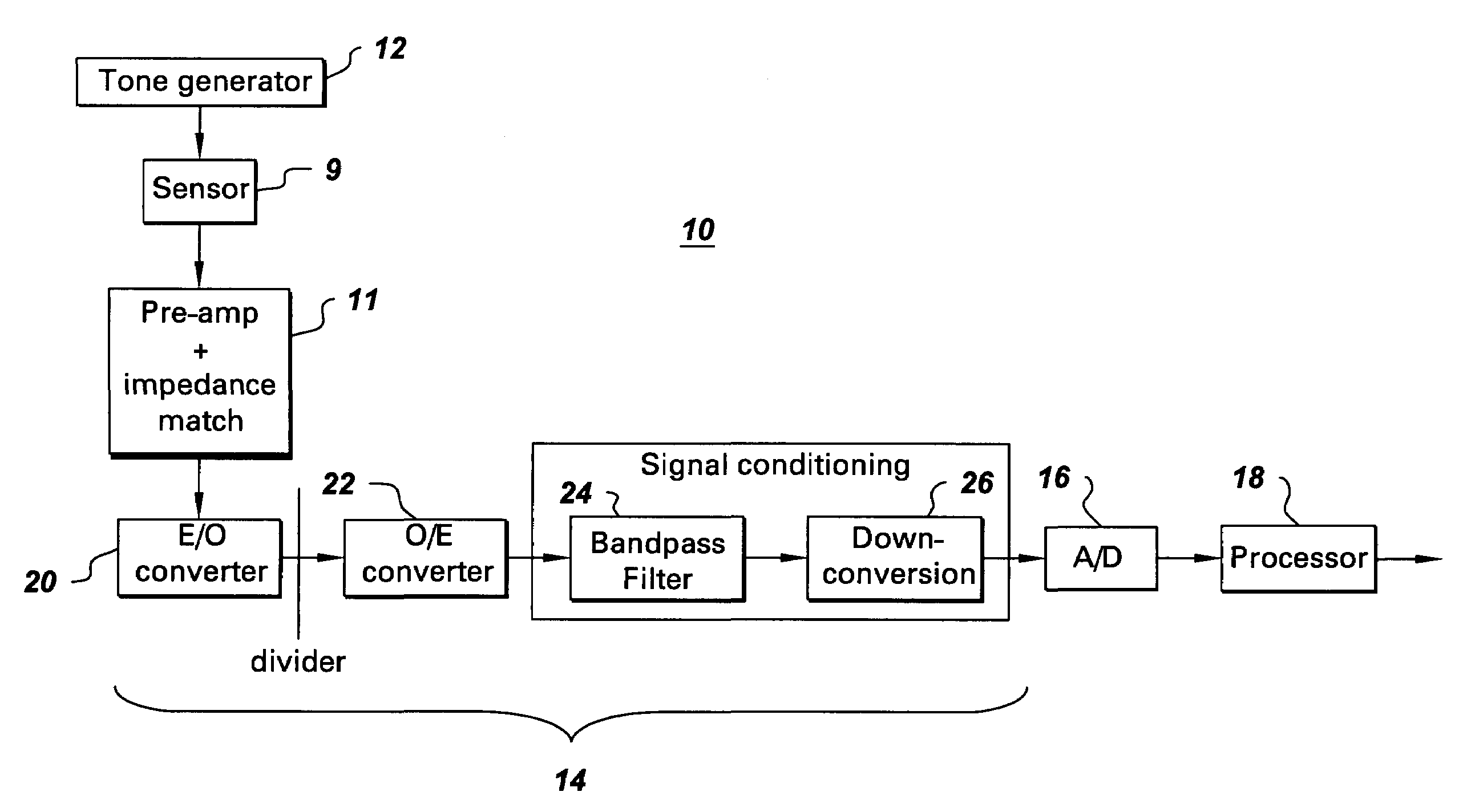
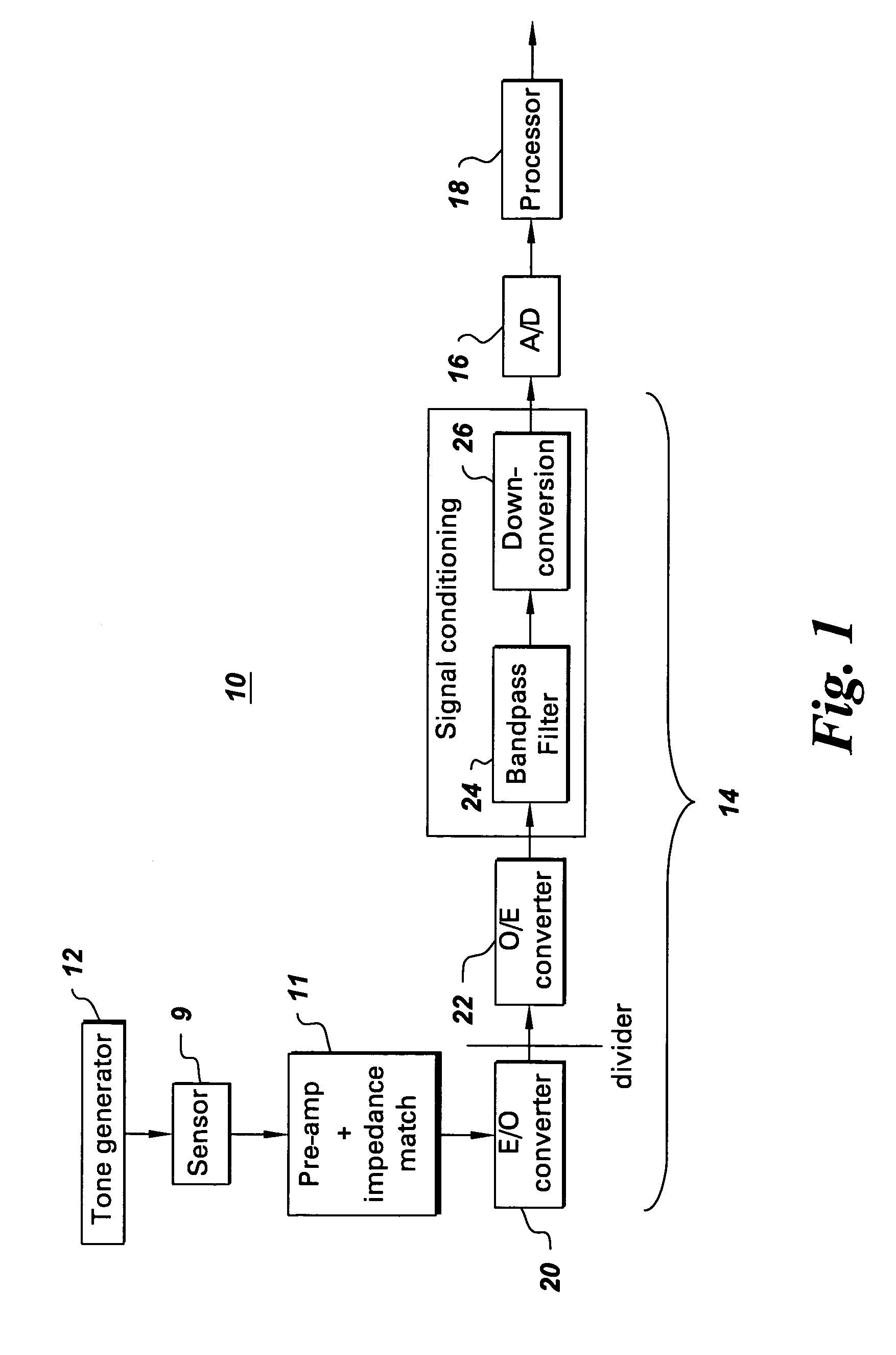
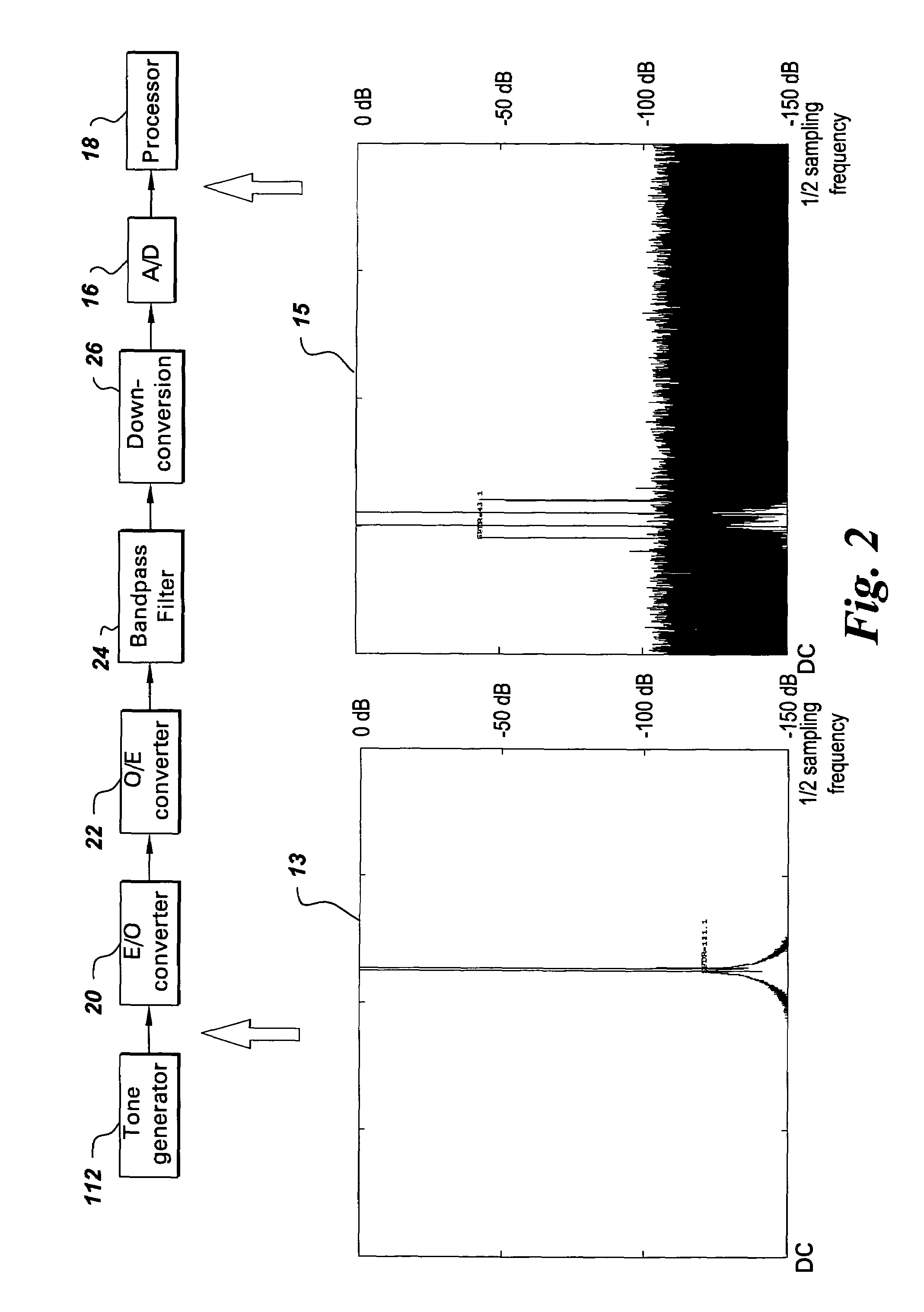
[0013]FIGS. 1 and 2 are block diagrams of linearization systems in accordance with several embodiments of the present invention. In these embodiments, linearization system 10 comprises: a tone generator 12 (FIG. 1) or 112 (FIG. 2) for providing at least two different RF tones, receiver path components 14 for processing the RF tones, an analog-to-digital converter 16 for converting the processed RF tones into digital signals, and a processor 18 for using the digital signals to train a linearization error compensation model prior to operational use of the linearization system. FIG. 1 additionally illustrates a sensor 9 and associated pre-amplification and impedance matching components 11 which would typically be present during operational use. Operational use is intended to mean use of the system in its operational mode. In one example wherein the linearization system comprises an imaging linearization system, operational use occurs when an object is being imaged. FIG. 2 additionally ...


PUM

PropertyMeasurementUnit
frequencyaaaaaaaaaa
frequenciesaaaaaaaaaa
trajectoryaaaaaaaaaa

Abstract

A system for training a linearization compensation model includes a tone generator for providing at least two different RF tones, receiver path components for processing the RF tones, an analog-to-digital converter for converting the processed RF tones into digital signals, and a processor for using the digital signals to generate the linearization error compensation model. The resulting compensation model is particularly useful in a linearization system which includes a receiver for measuring a signal, an electro-optical modulator configured for converting the measured signal to an optical signal, an optical-electrical detector configured for converting the optical signal to an analog electrical signal, an analog-to-digital converter for converting the analog electrical signal into a digital signal with the processor being used for removing linearization errors from the digital signal.

Description

BACKGROUND[0001]The invention relates generally to linearization systems and methods and more particularly to magnetic resonance imaging (MRI) linearization systems and methods.[0002]In magnetic resonance imaging, a chain of radio frequency (RF) components is typically used to condition analog waveforms received by coils in the imaging volume for digitization by an analog-to-digital converter. The chain of RF components typically includes amplifiers, attenuators, mixers, cables, electrical-to-optical modulators, optical-to-electrical receivers, and optical transmission structures such as fibers. Some of these components have non-linear responses which distort the signals. In particular, when optical systems include electrical-to-optical modulators, the modulators are a significant contributor to nonlinearization. Conventional approaches to minimizing nonlinearization in magnetic resonance imaging machines rely on careful design and selection of components, particularly variable gain...

Claims


Application Information

Patent Timeline
Patent Type & Authority Patents(United States)
IPC IPC(8): G01N24/00
CPCH03M1/1033H03M1/12
Inventor KOSTE, GLEN PETERZINSER, RICHARD LOUISMCKINNON, GRAEME COLIN
Owner GENERAL ELECTRIC CO
Why Eureka
Try Eureka