Dental articulator, method for producing dentures and method for adjusting the articulator in occlusion height in preparing the dentures
a technology of dentures and articulators, which is applied in the field of dental articulators, can solve the problems of frequent modification of the shape of new dentures, no standard in occlusion height (i.e. precise height in occlusion), and wear of dentures thus prepared, and achieves excellent fitness and proper adjustment of occlusion height.
- Summary
- Abstract
- Description
- Claims
- Application Information
AI Technical Summary
Benefits of technology
Problems solved by technology
Method used
Image
Examples
first embodiment
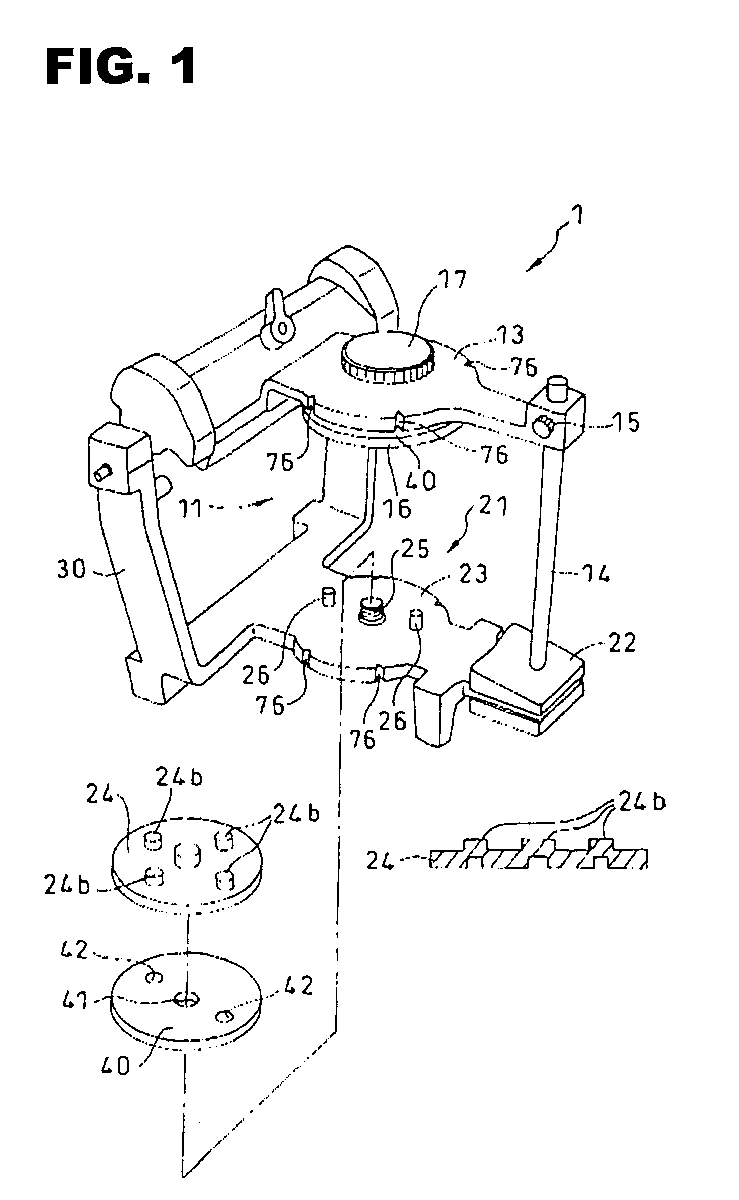
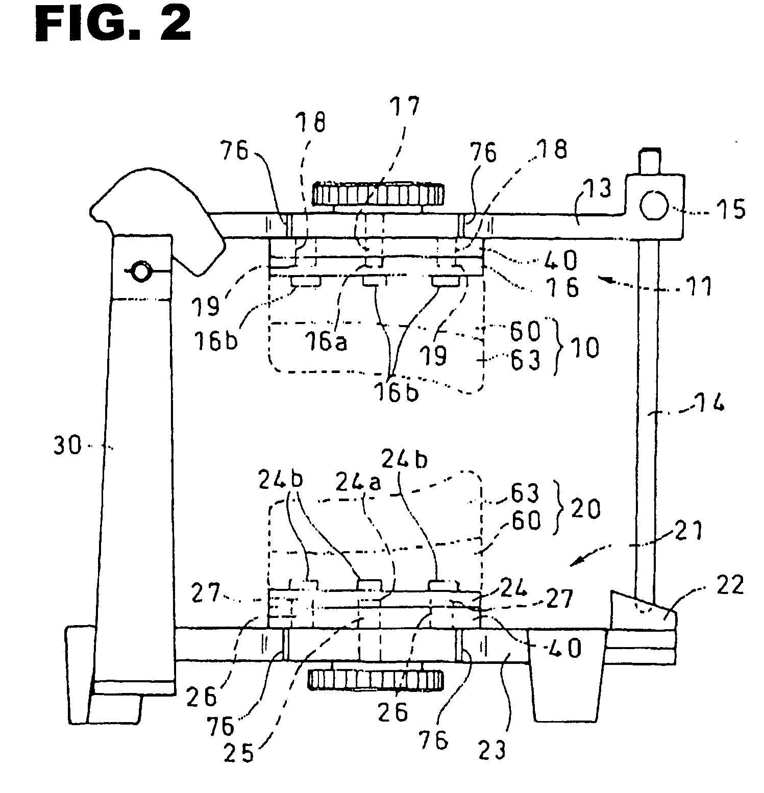
[0076]FIG. 1 shows a dental articulator 1 of the present invention, a side view of which articulator 1 is shown in FIG. 2. The articulator 1 is provided with a plurality of circular plates 40 each forming a height-control means.
[0077]As shown in FIGS. 3(a) and 3(b), the circular plates 40 varies in thickness. More specifically, in this first embodiment, four different kinds of the planar plates 40 are employed.
[0078]In addition to these planar plates 40, the articulator 1 of the present invention comprises: a lower frame 23 provided with a lower jaw model supporting portion 21 in its upper surface, wherein a lower jaw model 20 is detachably mounted on an upper surface of the lower jaw model supporting portion 21 through a selected one of the circular plates 40; a pair of stand portions 30 both provided upright in a rear portion of the lower frame 23; and, an upper frame 13 provided with an upper jaw model supporting portion 11 in its lower surface, wherein the upper fame 13 is artic...
second embodiment
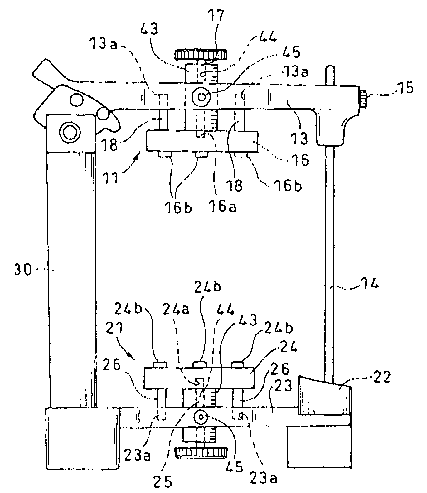
[0092]On the other hand, in the articulator of the present invention, the height-control means is constructed of a calibrated cylinder 43. In the lower frame 23, as is clear from FIG. 4, such calibrated cylinder 43 is vertically slidably mounted in the lower frame 23. In other words, the calibrated cylinder 43 passes through a through-hole of the lower frame 23 from under the lower frame 23 to have its upper end portion abut on a lower surface of the circular planar stage 24.
[0093]On the other hand, in the upper frame 13, likewise, another calibrated cylinder 43 is vertically slidably mounted in the upper frame 13. In other words, the calibrated cylinder 43 passes through a through-hole of the upper frame 13 from above the upper frame 13 to have its lower end portion abut on an upper surface of the circular planar stage 16. As is clear from FIG. 4, the calibrated cylinder 43 is provided with a vertical scale in its outer peripheral surface, and has its central through-hole threaded ...
third embodiment
[0102]In other words, in this third embodiment, as shown in FIG. 5, a pair of the stand portions 30 are disposed upright in a rear portion of the lower frame 23. Mounted on an upper surface of the lower frame 23 is the lower jaw model supporting portion 21 on which the lower jaw model 20 is detachably mounted.
[0103]In this third embodiment, the height-control means (such as the circular plates 40 in the first embodiment, and the calibrated cylinder 43 in the second embodiment) is constructed of an adjusting shaft 31. This shaft or height-control means 31 is disposed inside each of the stand portions 30 to have its lower portion and its upper portion threadably engaged with a lower stand 32 and an upper stand 35, respectively. A pair of dial members 34, 37 are threadably engaged with an intermediate threaded portion of the adjusting shaft 31. Due to this, it is possible for the dial members 34, 37 to move vertically relative to the adjusting shaft 31 when they 34, 37 are rotated rela...
PUM
 Abstract
Description
Claims
Application Information
 - R&D
- Intellectual Property
- Life Sciences
- Materials
- Tech Scout
- Unparalleled Data Quality
- Higher Quality Content
- 60% Fewer Hallucinations
Browse by: Latest US Patents, China's latest patents, Technical Efficacy Thesaurus, Application Domain, Technology Topic, Popular Technical Reports.
© 2025 PatSnap. All rights reserved.Legal|Privacy policy|Modern Slavery Act Transparency Statement|Sitemap|About US| Contact US: help@patsnap.com


