Tire demounting tool

a tire and tool technology, applied in the direction of tyre repairing, vehicle components, lifting devices, etc., can solve the problems of reducing the mechanical advantage provided by the tool, reducing the mechanical advantage of the tool, and proving less than satisfactory in providing an optimally functional tire working implemen

Active Publication Date: 2007-01-02
SUMMIT TOOL
View PDF51 Cites 11 Cited by
  • Summary
  • Abstract
  • Description
  • Claims
  • Application Information

AI Technical Summary

Benefits of technology

[0007]It is an object of the present inventio

Problems solved by technology

Known designs, while working well to an extent, have proven less than satisfactory in providing an optimally functional tire working implement.
Projections, however, carry a disadvantage in that they contact the wheel rim at a single point.
Rollers are undesirable in use because they are prone to movement during the working process and such movement can reduce the mechanical advantage provided by the tool.
With only one point of contact, the tool is prone to rocking or slipping on the rim during the tire removal procedure.
Rocking or slipping can dislodge the working tool and require the user to begin the working process anew.
At best, rocking or slipping necessarily causes the user to exert additional effort and concentration to maintain the working tool in its proper position.
While a downward end creates a more efficient lever, the downwardly turned tip, however, makes insertion difficult and requires inserting the tip at a sideways angle to the bead.
This process is time consuming, and requires significant effort.
Also, the straight design's range of motion is limited by contact with the tread of the tire.
This may prevent the user from demounting the tire, or, in the least require greater effort to pry the rim free.

Method used


Image

  • Tire demounting tool
  • Tire demounting tool
  • Tire demounting tool

Examples


Embodiment Construction

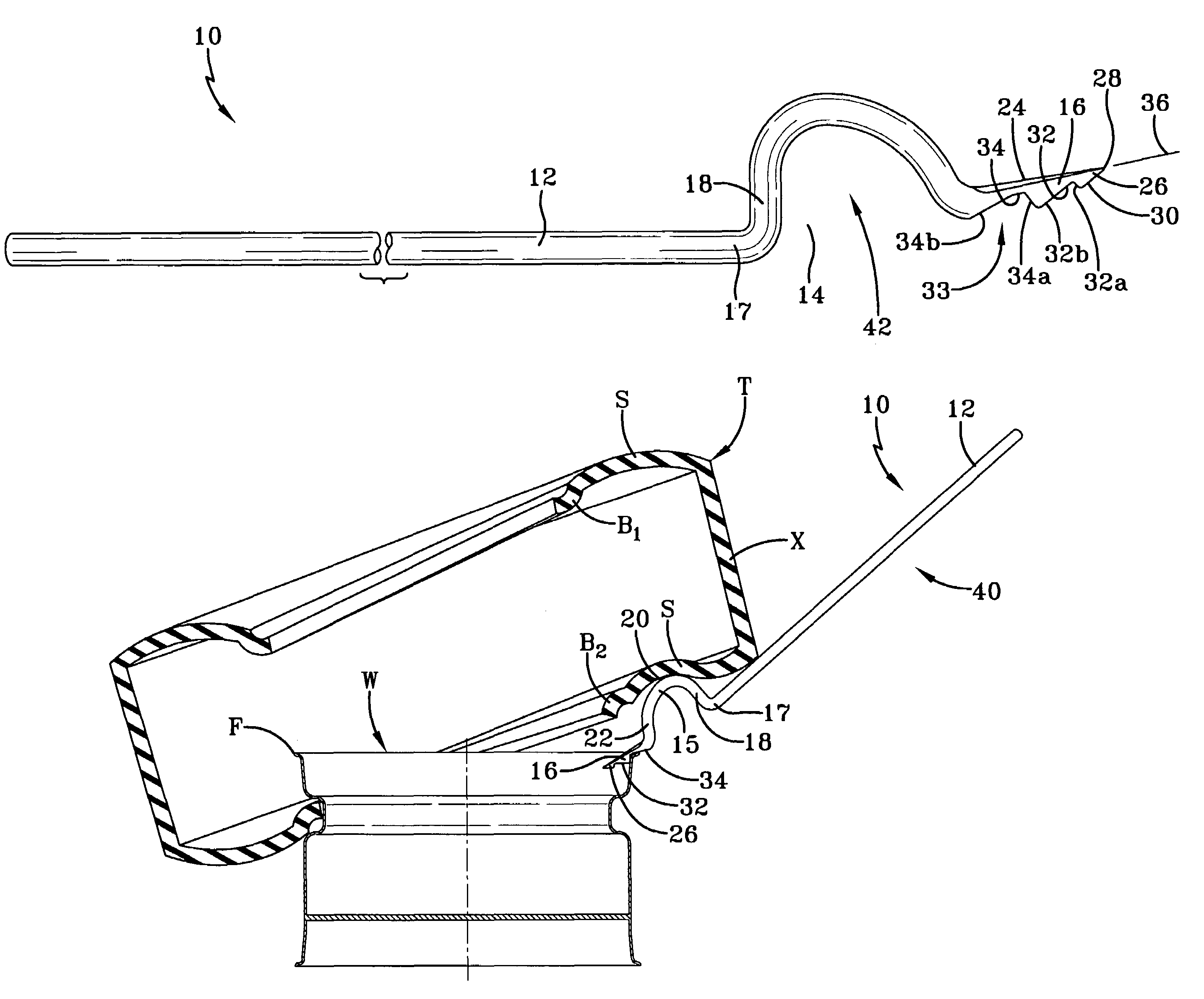
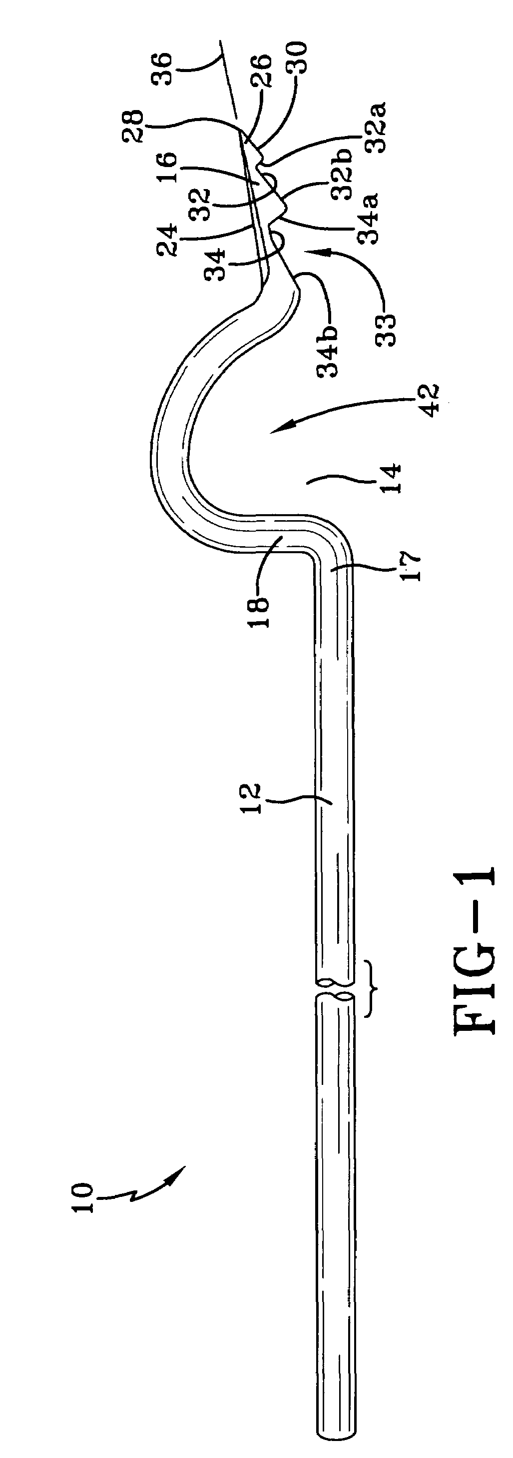
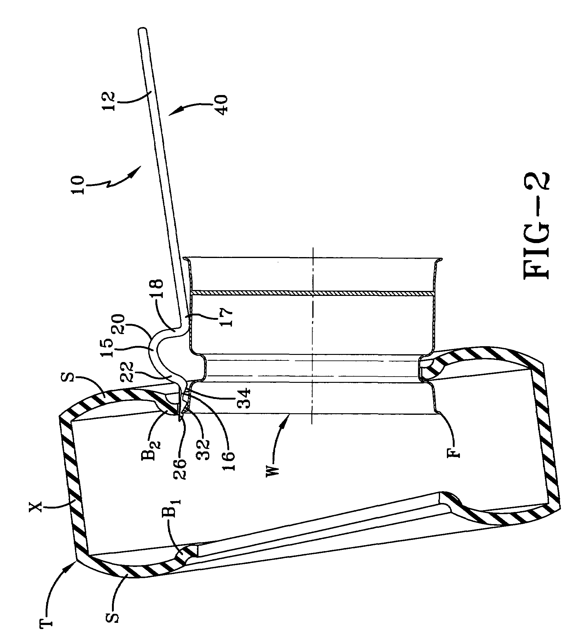
[0016]A tire demounting tool according to the concepts of the present invention is depicted in the drawings and generally indicated therein by the numeral 10. Tire demounting tool 10 generally includes a handle 12, a head, generally indicated by the numeral 15, extending from handle 12 and a bill 16 extending from head 15. The bill 16 is insertable between a second bead B2 of a tire T and a wheel rim W to pry the second bead B2 over the flange F of wheel rim W to demount tire T from wheel rim W. It will be understood that a separate tool is used to demount the first bead B1 of the tire T. It will be understood that reference to a first or second bead does not refer to a particular bead on the tire, but to the order in which they are removed to demount tire T from wheel rim W. Consequently, the first bead, B1, is the first bead to be removed from wheel rim W. The second bead, B2, is removed after first bead B1 to completely release tire T from wheel rim W.

[0017]With reference to FIG....


PUM


Abstract

A tire demounting tool for demounting a second bead of a tire from a rim having a flange, the tire demounting tool including a handle; a head extending radially outward as it extends axially outward from the handle; a bill extending axially outward from the head, wherein the bill includes a tip insertable between the second bead and the rim and wherein the head extends radially outward relative to the bill to capture the second bead when the bill is inserted between the rim and the second bead.

Description

TECHNICAL FIELD[0001]The present invention relates generally to a tool for demounting a tire from a rim. More particularly, the present invention relates to a demounting tool used to demount the second bead of a tire from the rim.BACKGROUND OF THE INVENTION[0002]From time to time, pneumatic tires require repair or replacement. To service such tires, the tire must be removed from the wheel rim. A variety of tools have been developed and utilized to facilitate the working of tires. Such tools typically comprise an elongate bar having a handle and a working end adapted to be inserted between the tire bead and wheel rim. The working end of the tool frequently has a flattened or tapered portion to facilitate insertion of the working end between the tire bead and the wheel rim.[0003]To utilize the implement, the tool working portion is inserted manually between the bead of the tire and its associate wheel rim. Thereafter, the user applies pressure on the handle and moves a portion of the ...

Claims


Application Information

Patent Timeline
IPC IPC(8): B60C25/02
CPCB60C25/02
Inventor KLISKEY, ROGER
Owner SUMMIT TOOL
Why Eureka
Try Eureka