
Module connector

a module connector and connector technology, applied in the direction of coupling contact members, fixed connections, coupling device connections, etc., can solve the problems of high cost and difficult space saving

Inactive Publication Date: 2006-12-26
SMK CORP
View PDF13 Cites 8 Cited by
  • Summary
  • Abstract
  • Description
  • Claims
  • Application Information

AI Technical Summary

Benefits of technology

This solution simplifies the connection process, reduces costs by using inexpensive FFCs, and eliminates layout restrictions, providing a thinner and more space-efficient connection method for small-sized modules.

Problems solved by technology

There have also been other problems.
For example, higher costs are required since expensive FPCs 12 are available.
Also, forming the circuit pattern for connecting the module 10 with an FPC 12 has many restrictions as to circuit pattern layout and thus makes space saving difficult.

Method used


Image

  • Module connector
  • Module connector
  • Module connector

Examples


Embodiment Construction

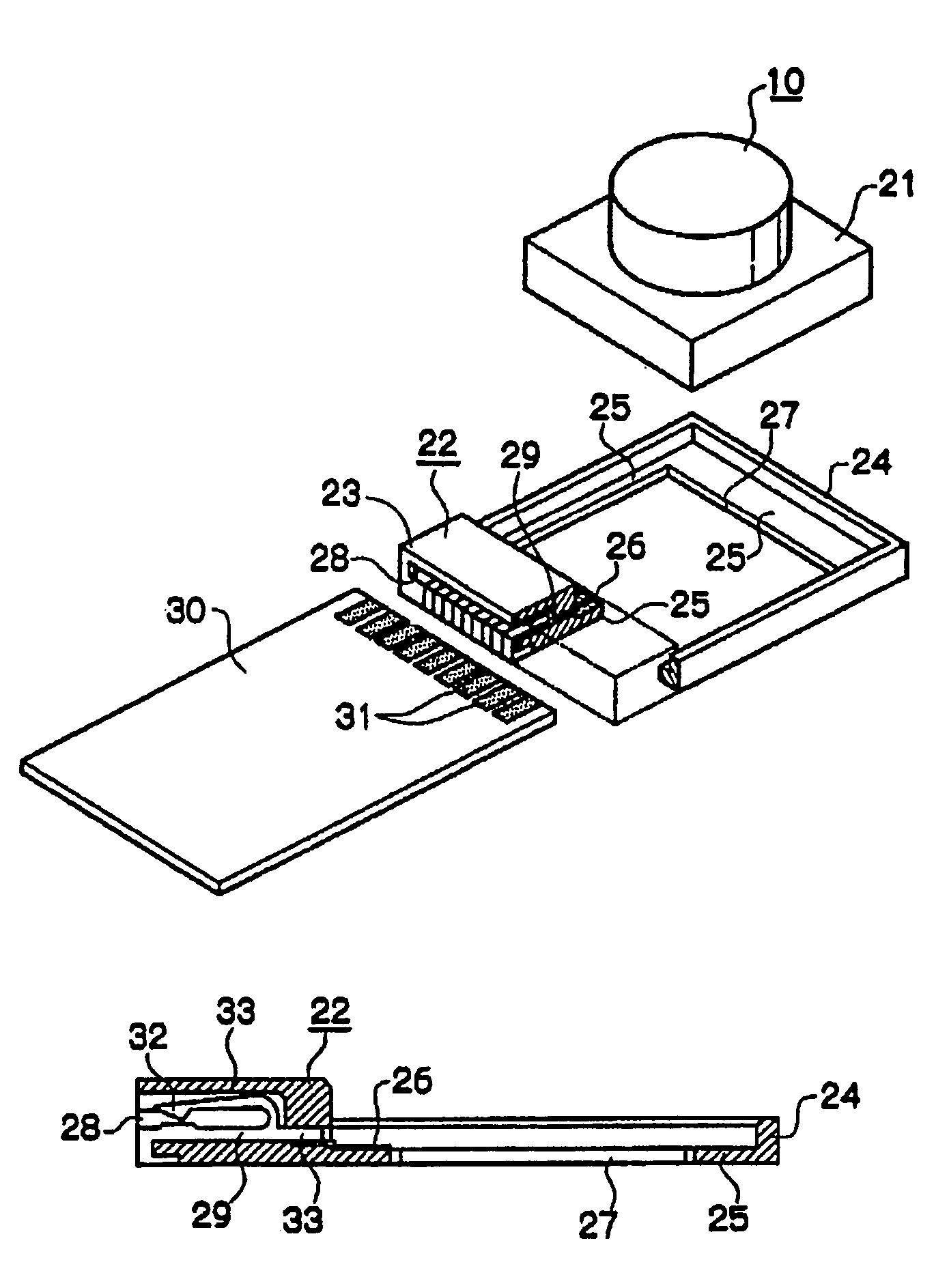
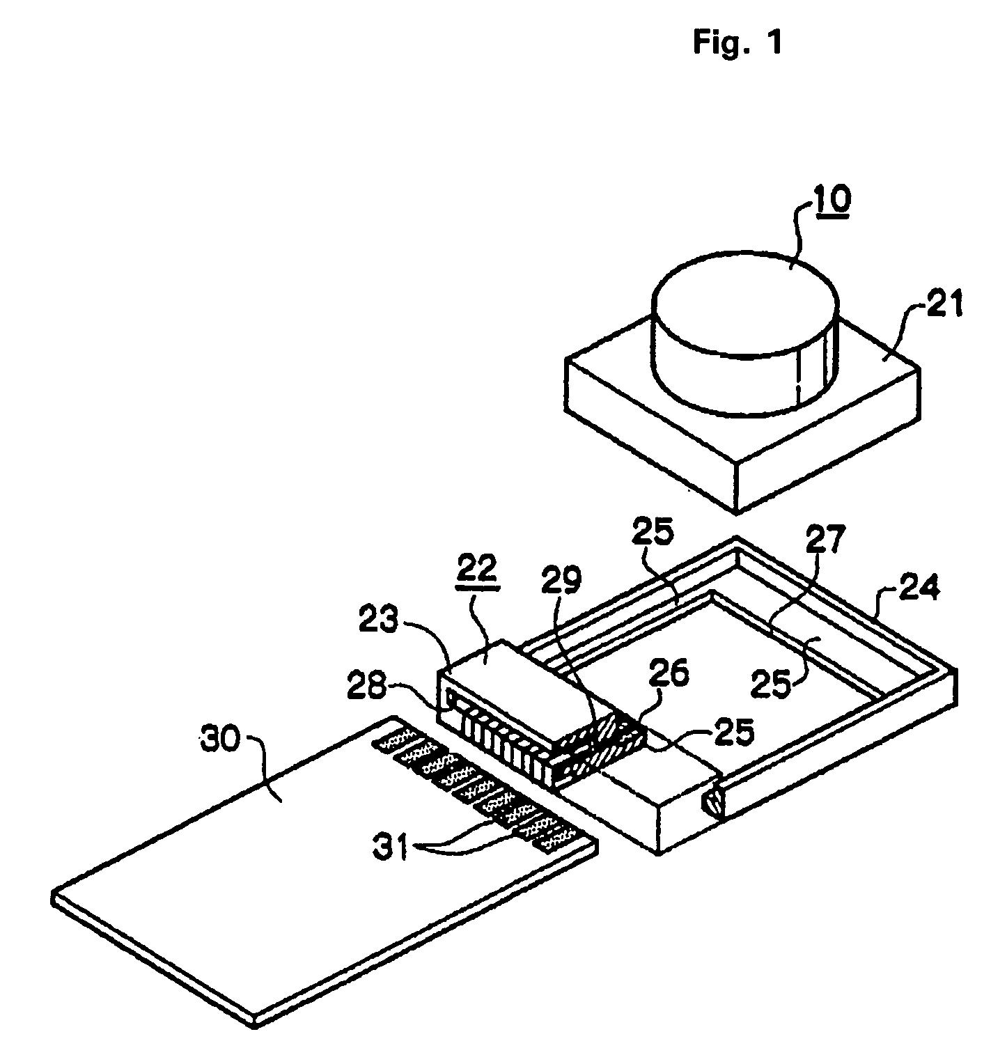
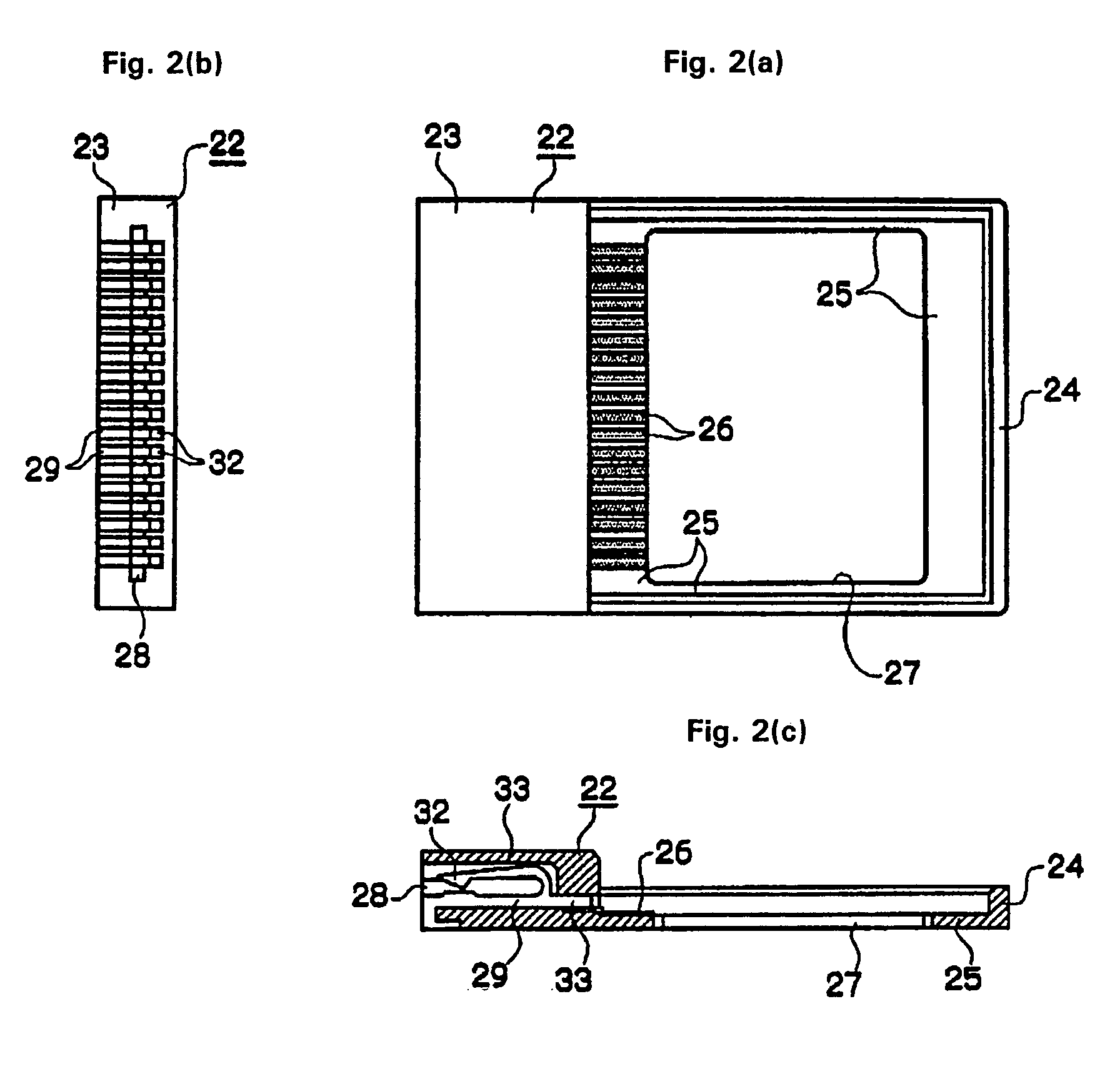
[0026]In the present invention, a module base connector formed as a thin plate is interposed between a plurality of terminals of a small-sized module and a wiring member. This module base connector includes a fitting frame and a connector housing. The fitting frame has terminals electrically connected to a plurality of terminals formed on a module housing of the module. The connector housing has connection terminal pieces each connected at one end to the terminals of the fitting frame and at the other end to terminals of the wiring member.

[0027]The connector housing and the fitting frame are formed integrally. A module fitting part formed on the fitting frame is provided with a terminal pattern electrically connected to the plurality of terminals formed on the module housing. The connector housing is provided with connection terminal pieces each having an elastic contact portion connected at one end to a wiring member such as a flexible flat cable and a press contact portion connect...


PUM


Abstract

A module connector has a simple module base connector capable of being used instead of a module socket, thereby allowing connection to wiring members such as an inexpensive flexible flat cable. The module base connector, formed as a thin plate, is interposed between a plurality of terminals of a small-sized module and a wiring member. This base connector includes a fitting frame and a connector housing which are formed integrally. A module fitting part of the fitting frame is provided with a terminal pattern electrically connected to the plurality of terminals of the module housing. The connector housing is provided with connection terminal pieces each having an elastic contact portion connected at one end to the wiring member of a flexible flat board, and a press contact portion connected at the other end to the terminal pattern.

Description

CROSS-REFERENCE TO RELATED APPLICATION[0001]This application claims priority of Japanese Patent Application Number 2004-031617, filed Feb. 9, 2004, which is hereby incorporated by reference in its entirety.BACKGROUND OF THE INVENTION[0002]1. Field of the Invention[0003]The invention relates to a module connector for connecting a small-sized module having a number of terminals, such as a CCD, a display, and a microphone intended for a cellular phone, to a wiring member such as a flexible flat cable.[0004]2. Description of the Related Art[0005]Among known examples of attaching a module 10 having a number of terminals and an extremely compact configuration to a wiring sheet is one such as shown in FIGS. 8(a) and 8(b) (see Japanese Unexamined Patent Application Publication No. 2003-92168).[0006]In these diagrams, when the module 10 is fitted into a socket housing 13 of a module socket 11 from above, the lock pieces 15 of lock springs 14 arranged on the internal surfaces of the socket ho...

Claims


Application Information

Patent Timeline
Patent Type & Authority Patents(United States)
IPC IPC(8): H01R12/00H01R33/74H01R13/33H01R13/514
CPCH01R12/62H01R12/7076H01R13/514
Inventor OHSAWA, FUMIOHAYASHI, MASAKIASAI, KIYOSHI
Owner SMK CORP
Learn More