Line thermal head printer device
a printer device and thermal head technology, applied in typewriters, printing, instruments, etc., can solve the problems of large size and considerable space, and achieve the effect of remarkably small printer device siz
- Summary
- Abstract
- Description
- Claims
- Application Information
AI Technical Summary
Benefits of technology
Problems solved by technology
Method used
Image
Examples
first embodiment
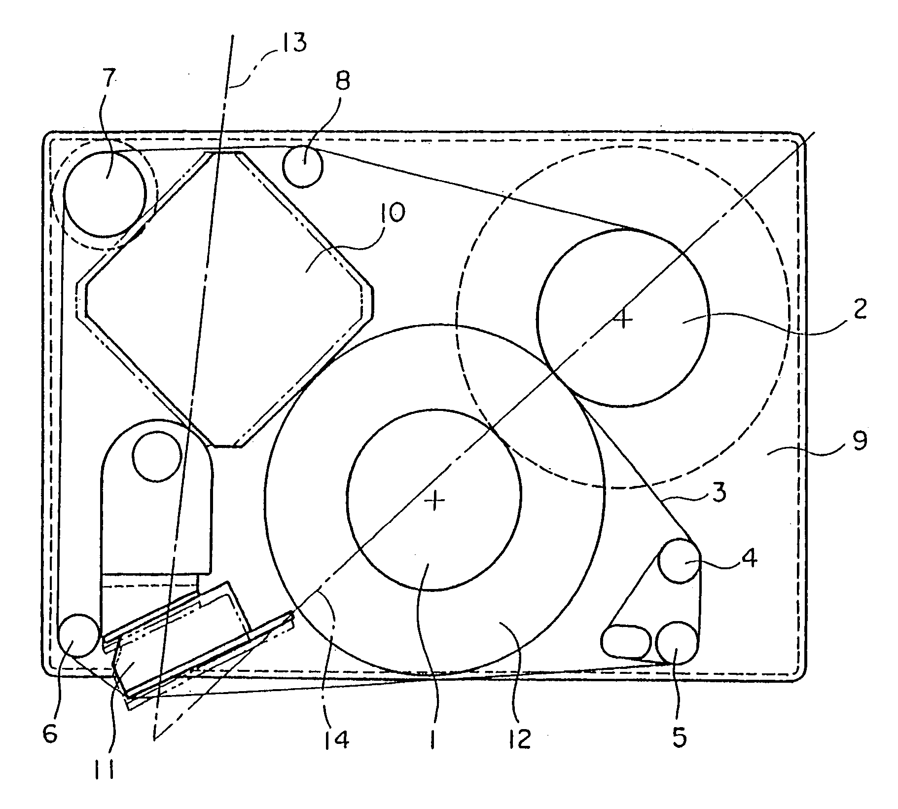
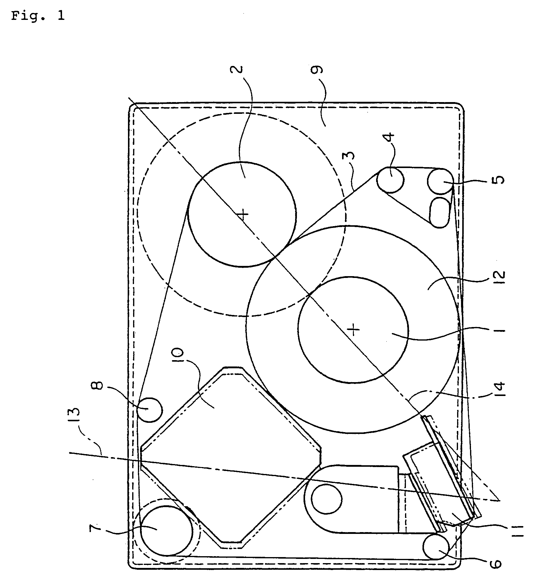
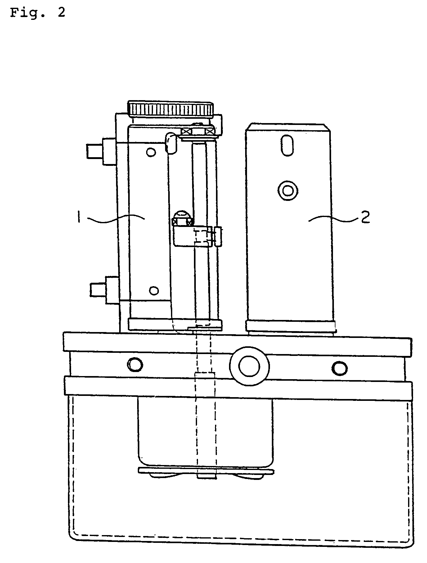
[0034]FIG. 1 is a plan view and FIG. 2 is a right-hand side view, that is, a side view seen from the right-hand side of FIG. 1, both of a line thermal head printer device of a first embodiment according to the present invention. This first embodiment is an example where the present invention is applied to a printer device having a fixed type line thermal head. In FIGS. 1 and 2, numeral 1 designates a ribbon tape unwinding drive shaft and numeral 2 a ribbon tape winding drive shaft. The ribbon tape unwinding drive shaft 1 is arranged on one side of a line thermal head 11 to be described later. The ribbon tape winding drive shaft 2 is arranged on an upper corner portion on the right-hand side of FIG. 1. On the left-hand side upper corner portion opposite to the ribbon tape winding drive shaft 2, a stepping motor 10, to be described later, is arranged.
[0035]A ribbon tape unwinding reel of a ribbon tape master roll 12 is fitted to the ribbon tape unwinding drive shaft 1 so that the ribb...
second embodiment
[0042]FIG. 3 is a plan view and FIG. 4 is a right-hand side view, that is, a side view seen from the right-hand side of FIG. 3, both of a line thermal head printer device of a second embodiment according to the present invention. This second embodiment is an example where the present invention is applied to a printer device having a movable type line thermal head. In FIGS. 3 and 4, numeral 21 designates a ribbon tape unwinding drive shaft and numeral 22 a ribbon tape winding drive shaft. The ribbon tape unwinding drive shaft 21 is arranged on the right-hand side lower corner portion of FIG. 3. On the left-hand side lower corner portion opposite to the ribbon tape unwinding drive shaft 21, a line thermal head 32, to be described later, is arranged. The ribbon tape winding drive shaft 22 is arranged on the upper central portion of FIG. 3 and, on the left-hand side upper corner portion adjacent to the ribbon tape winding drive shaft 22, a stepping motor 31, to be described later, is ar...
PUM
 Abstract
Description
Claims
Application Information
 - R&D
- Intellectual Property
- Life Sciences
- Materials
- Tech Scout
- Unparalleled Data Quality
- Higher Quality Content
- 60% Fewer Hallucinations
Browse by: Latest US Patents, China's latest patents, Technical Efficacy Thesaurus, Application Domain, Technology Topic, Popular Technical Reports.
© 2025 PatSnap. All rights reserved.Legal|Privacy policy|Modern Slavery Act Transparency Statement|Sitemap|About US| Contact US: help@patsnap.com


