
Control circuit for monitoring and maintaining a bootstrap voltage in an N-channel buck regulator

a control circuit and buck regulator technology, applied in the field of switching regulators, can solve problems such as output voltage dropout, regulated output voltage may not be regulated up to the desired value,

Active Publication Date: 2006-12-05
MICREL
View PDF2 Cites 68 Cited by
  • Summary
  • Abstract
  • Description
  • Claims
  • Application Information

AI Technical Summary

Benefits of technology

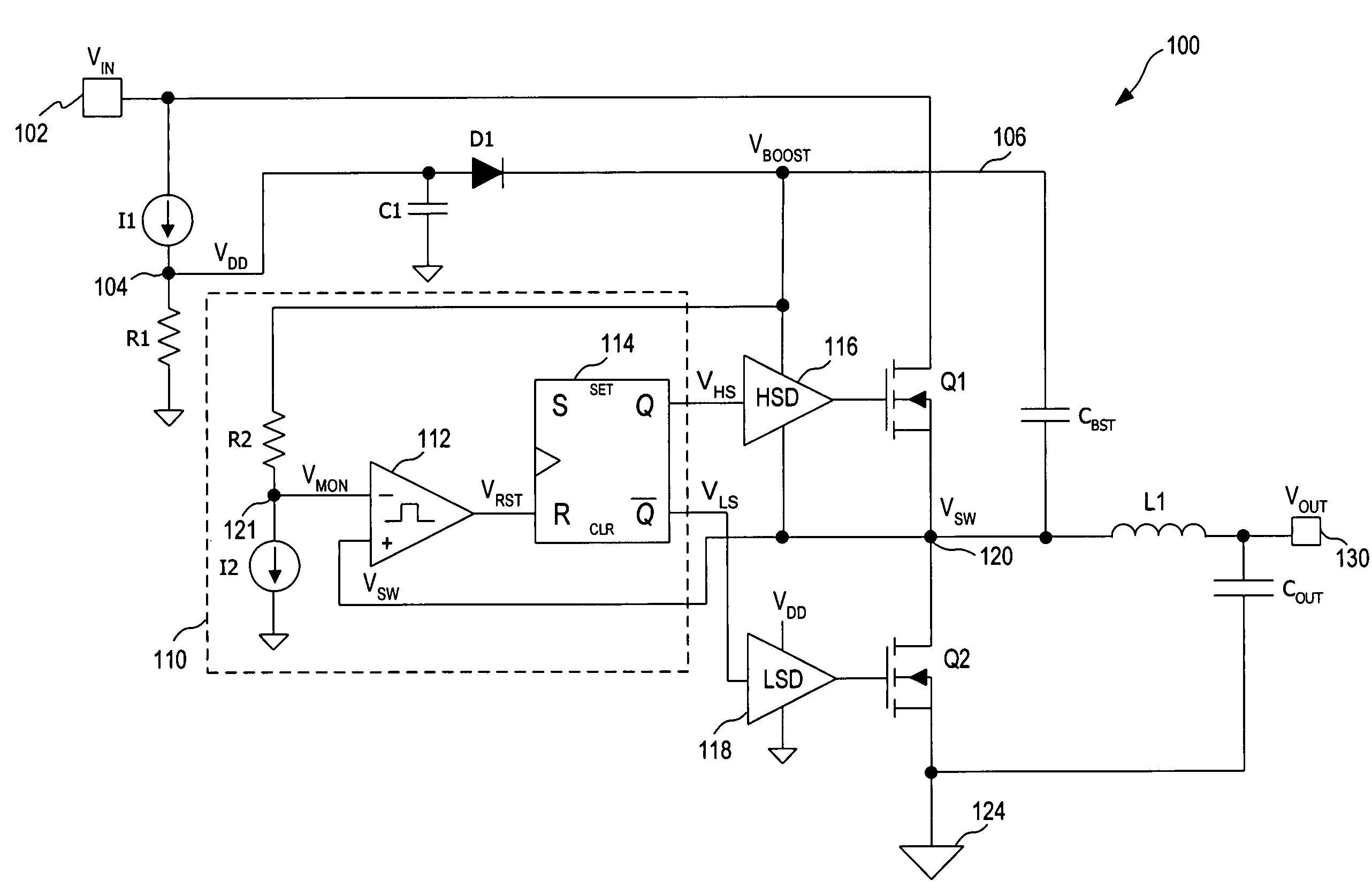
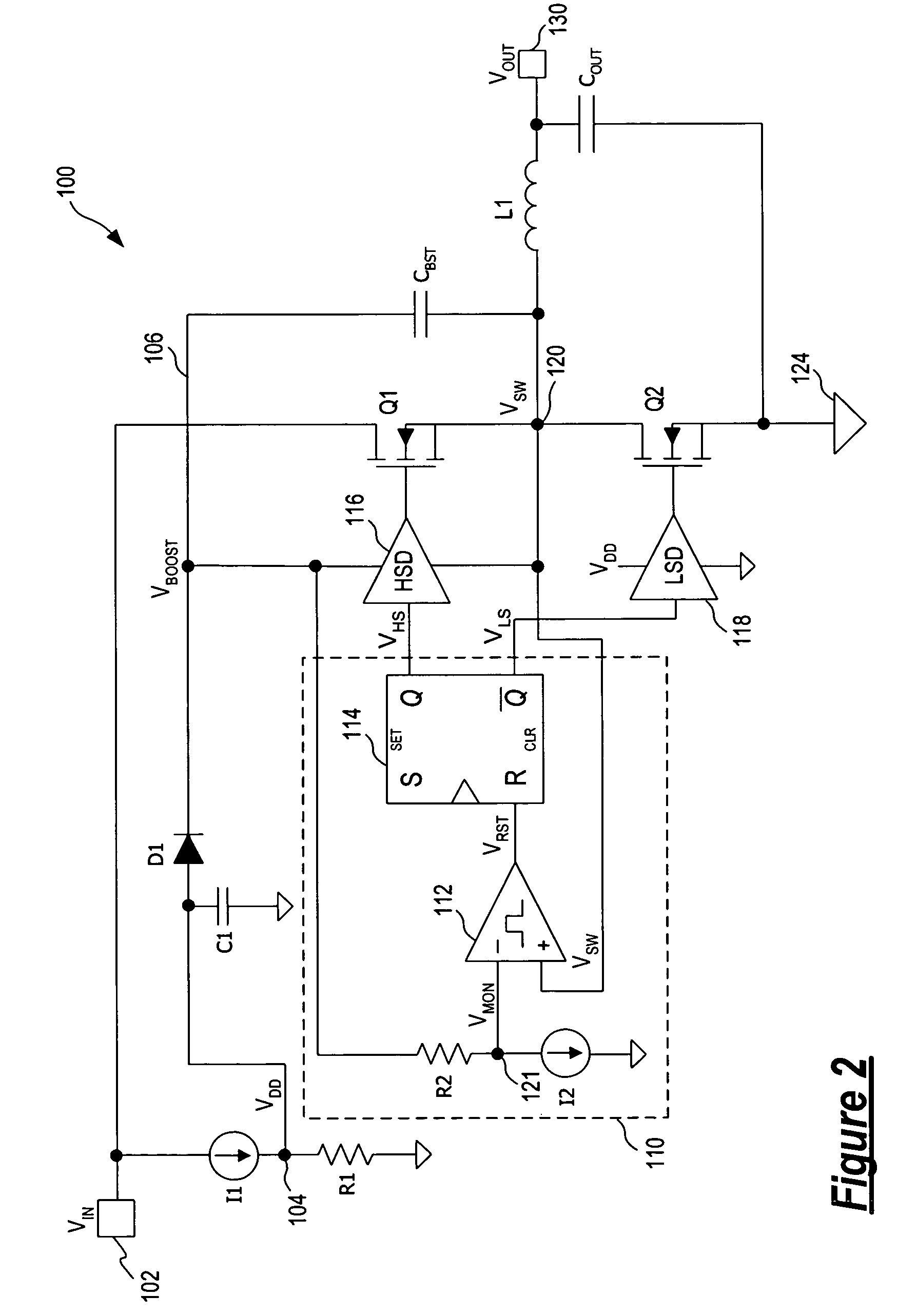
[0009]According to one embodiment of the present invention, a control circuit is incorporated in a switching regulator for monitoring and maintaining the bootstrap voltage to allow the switching regulator to operate at 100% or near 100% duty cycle.

Problems solved by technology

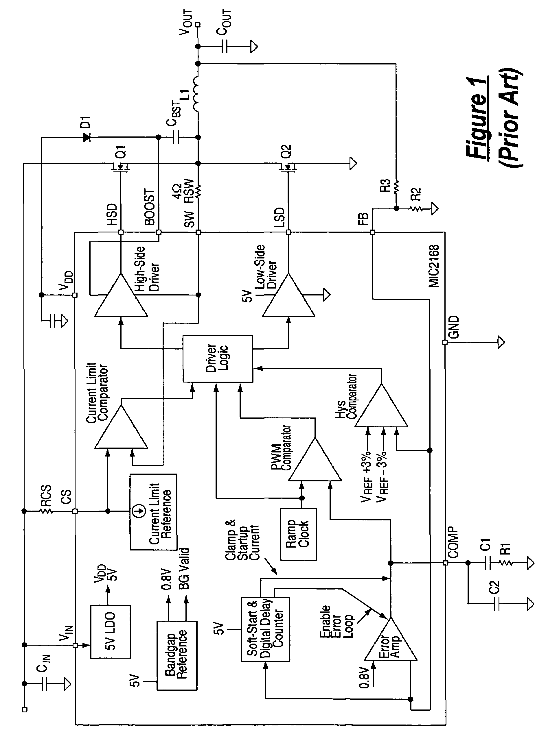
Because of the required voltage headroom, when the input voltage drops, the regulated output voltage may not be regulated up to the desired value.
Output voltage dropout thus results.

Method used


Image

  • Control circuit for monitoring and maintaining a bootstrap voltage in an N-channel buck regulator
  • Control circuit for monitoring and maintaining a bootstrap voltage in an N-channel buck regulator
  • Control circuit for monitoring and maintaining a bootstrap voltage in an N-channel buck regulator

Examples


Embodiment Construction

[0017]In accordance with the principles of the present invention, a control circuit for use in an N-channel buck switching regulator monitors the bootstrap voltage of the switching regulator and provides a control signal to cause the driver circuits of the switching regulator to switch the power switches when the bootstrap voltage has decayed below a predetermined level. The switching action of the power switches refreshes the bootstrap voltage. In this manner, the switching regulator can maintain a duty cycle approaching 100% to avoid voltage dropout while maintaining the necessary bootstrap voltage for powering the high-side driver circuit driving the high-side power switch. In operation, depending on the current draw on the bootstrap voltage, the control circuit will allow the N-channel buck switching regulator to maintain a long on-time, skipping switching cycles until the bootstrap voltage decays to a sufficient level to require a recharge. A high duty cycle approaching 100% ca...


PUM


Abstract

A control circuit is incorporated in a switching regulator for monitoring and maintaining a bootstrap voltage to allow the switching regulator to operate at or near 100% duty cycle. The control circuit includes a circuit receiving the bootstrap voltage and generating a monitor voltage, a comparator circuit receiving the monitor voltage and a first voltage indicative of a switching output voltage and generating an output signal having a first state when the monitor voltage is equal to or less than the first voltage, a logic circuit receiving the output signal and generating drive control signals to driver circuits driving the high-side and low-side power switches. The logic circuit generates the drive control signals in response to the output signal of the comparator circuit having the first state to cause the high-side power switch to turn off and the low-side power switch to turn on, thereby recharging the bootstrap voltage.

Description

FIELD OF THE INVENTION[0001]The invention relates to switching regulators and, in particular, to a buck switching regulator including bootstrap voltage monitoring to achieve very high duty cycles.DESCRIPTION OF THE RELATED ART[0002]A switching regulator, also referred to as a switching mode power supply, provides power supply function through low loss components such as capacitors, inductors, and transformers, and power switches that are turned on and off to transfer energy from the input to the output in discrete packets. A feedback control circuit is used to regulate the energy transfer to maintain a constant output voltage within certain load limits of the circuit. A switching regulator can be configured to step up the input voltage or step down the input voltage or both. Specifically, a buck switching regulator steps down the input voltage while a boost switching regulator steps up the input voltage. A buck-boost switching regulator provides both step-up and step-down functions....

Claims


Application Information

Patent Timeline
Patent Type & Authority Patents(United States)
IPC IPC(8): G05F1/613G05F1/40
CPCH02M3/156H02M1/08
Inventor GALINSKI, III, MARTIN F.
Owner MICREL
Learn More