Method and apparatus for intravascular two-dimensional ultrasonography

Inactive Publication Date: 2006-11-07
BOSTON SCI SCIMED INC
View PDF84 Cites 16 Cited by
  • Summary
  • Abstract
  • Description
  • Claims
  • Application Information

AI Technical Summary

Benefits of technology

[0005]According to the present invention, a method for imaging the interior of a blood vessel comprises scanning an ultrasonic signal in a preselected pattern about said interior. By receiving ultrasonic energy reflected from the interior surface of the vessel, including any stenosis or occlusion present, an image or profile of the blood vessel may be produced. Conveniently, the ultrasonic signal is generated by a transducer located at the distal end of a vascular catheter comprising a flexible tubular member. The transducer may be manipulated directly to sweep the ultrasonic signal in a desired pattern, including radial, planar, and conical. Alternatively, the transducer may be fixed within the catheter and a reflective surface manipulated to sweep the ultrasonic signal in a desired pattern. The imaging method of the present invention is advantageously combined with interventional therapeutic techniques to reduce vascular stenosis, where the stenosis may be imagined prior to, during, and after intervention to help direct the interventional activity to where it will be most effective.

Problems solved by technology

Such devices, however, have been relatively large and inflexible and are completely unsuitable for use within the vascular system of the human body.
In addition, there is no provision for guiding such devices into specific branches of blood vessels.

Method used


Image

  • Method and apparatus for intravascular two-dimensional ultrasonography
  • Method and apparatus for intravascular two-dimensional ultrasonography
  • Method and apparatus for intravascular two-dimensional ultrasonography

Examples


embodiment 11

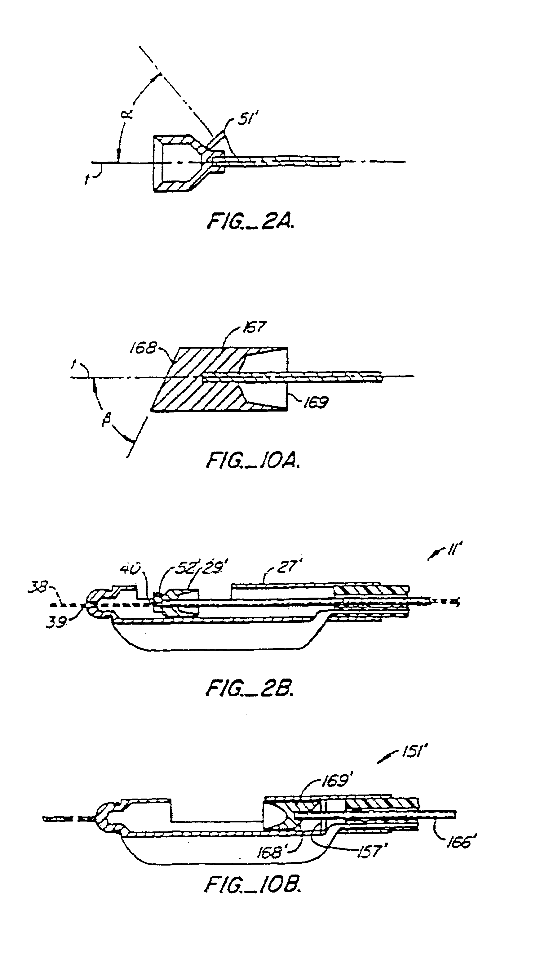
[0046]An alternate embodiment 11′ of catheter 11 is illustrated in FIG. 2B. The catheter 11′ is similar to that of catheter 11, except that it is modified to permit insertion of the catheter 11′ over a movable guidewire 38 and the cutter 29′ is reversed to provide cutting when the cutter is translated in the proximal (rearward) direction. The modifications include providing a penetration 39 in the distal tip of housing 27 and an axially aligned penetration 40 in the cutter 29′. The ultrasonic transducer 52′ is mounted on the distal end of cutter 29′, and torque cable 32′ includes an axial lumen. In this way, the catheter 11′ is inserted by conventional techniques over guidewire 38, with the guidewire passing through penetrations 39 and 40 and the lumen of torque cable 32°.

[0047]Another embodiment of the catheter apparatus of the present invention is shown in FIGS. 8 and 9. Many of the parts are very similar to the parts utilized in the embodiment of the invention shown in FIG. 1 and...

embodiment 151

[0056]An alternate embodiment 151′ of catheter 151 is illustrated in FIG. 10B. The catheter employs a fixed ultrasonic transducer 157′, but cutter 169′ is reversed to provide for forward cutting. Forward cutting is often advantageous in that severed stenotic material is less likely to become entangled with the torque cable 166′. Ultrasonic transducer 157′ will be provided with a central penetration to allow passage of the torque cable 166′, and said transducer will be located at the proximal end of housing 27′, but otherwise the construction of catheter 151′ will be the same as catheter 151.

[0057]In a further modification, it is possible to secure the ultrasonic transducer 157′ onto the torque cable 166′. Wires connecting the transducer 157′ to the external receiver and transmitter would then be attached to the torque cable 166′ and coupled to the outside in a manner similar to that illustrated in FIGS. 1–4. The transducer 157′ would then translate axially in tandem with the cutter ...


PUM


Abstract

A catheter is provided for insertion in the he blood vessel of a patient for ultrasonically imaging the vessel wall. The catheter includes a tubular element and an internally housed drive cable for effective circumferential scan about the catheter of an ultrasonic generating means. Both the tubular element and the drive cable are of a size and flexibility sufficient to permit their introduction into the vessel and subsequent advancement through the vessel to the location of the vessel wall where imaging is desired.

Description

[0001]This application is a continuation of U.S. patent application Ser. No. 10 / 177,897, filed on Jun. 20, 2002, now U.S. Pat. No. 6,572,554 which is a continuation of U.S. patent application Ser. No. 09 / 816,586, filed on Mar. 23, 2001 (now U.S. Pat. No. 6,409,673), which is a continuation of U.S. patent application Ser. No. 09 / 300,168, filed on Apr. 27, 1999 (now U.S. Pat. No. 6,221,015), which is a continuation of U.S. patent application Ser. No.08 / 911,635, filed on Aug. 15, 1997 (now U.S. Pat. No. 5,902,245), which is a continuation of U.S. patent application Ser. No. 08 / 467,178, filed on Jun. 6, 1995 (now U.S. Pat. No. 5,865,178), which is a continuation of U.S. patent application Ser. No. 08 / 162,412, filed on Dec. 3, 1993 (now U.S. Pat. No. 5,676,151), which is a divisional of U.S. patent application Ser. No. 08 / 014,906, filed on Feb. 1, 1993 (now U.S. Pat. No. 5,313,949), which is a continuation of U.S. patent application Ser. No. 07 / 826,260, filed on Jan. 24, 1992 (now abando...

Claims


Application Information

Patent Timeline
IPC IPC(8): A61B8/12A61B6/00A61B8/00A61B8/14A61B17/22A61B19/00A61M25/00
CPCA61B5/02007A61B8/12A61B8/4461A61B17/22012A61B17/320783A61B8/445A61B2017/00924A61B2017/22038A61B2017/22045A61B2017/22052A61B2017/22074A61B2017/22078A61B2019/5238A61B2019/528A61B2090/376A61B2090/3784
Inventor YOCK, PAUL G.
Owner BOSTON SCI SCIMED INC
Why Eureka
Try Eureka