
Multiple self locking hinge assembly

a hinge assembly and hinge technology, applied in the field of folding hinges, can solve the problems of inability to integrate all the novel aspects of the prior art, inability to make effective collapsing hinge devices, and inability to meet the needs of users, so as to achieve convenient transportation and storage, reduce the size of the device, and improve the effect of lateral stability and strength

Inactive Publication Date: 2006-11-07
FULCRUM SPORTS
View PDF16 Cites 26 Cited by
  • Summary
  • Abstract
  • Description
  • Claims
  • Application Information

AI Technical Summary

Benefits of technology

[0010]The invention consists of an ingenuously designed set of self locking hinges connected via a connection means. The invention can be used in a number of applications. The hinge can be used in conjunction with poles for many common applications such as crutches, walkers, golf bag carriages, baby carriages, and similar devices. The invention can come in any size and shape depending on the application needs. One key advantage of the invention is that it can be opened and closed with single hand and with one fluid motion. In the case of a crutch a person simply holds the upper half of the crutch containing the handle and releases the bottom half of the crutch. The self locking hinge assembly engages once the bottom half of the crutch is in place, that is, lined up end to end with the top half of the crutch (See FIG. 5 and FIG. 6). The hinge assembly is designed such that the force, typically gravity, which is used to bring the lower half of the crutch in orientation with the top half of the crutch is sufficient to cause the self locking latches to pivot sufficiently to engage the hinge assembly. Although it is not necessary one may wish to manually pivot the self locking latches to engage the hinge assembly without loosing the ability to use the invention as a single hand operation. One can easily disengage the assembly by applying pressure by the finger of one's hand on to the lever causing the self locking latches to pivot and thus disengage the hinge assembly. The single hand operation of the hinge assembly is desirable and convenient in many applications, especially in the case with one using a crutch as one would have an injury and as such he or she may need the convenience of a single hand operation.
[0011]Another advantage of the invention is that it allows for a crutch, or other multiple poled devices, to be broken down to a compact size for easy transportation and storage. This is desirable in almost all applications, especially with crutches. If needed several hinge assemblies may be placed in the multiple poled device thereby allowing the device to be folded a number of times, further reducing the size of the device for transport and storage. Lastly, the connection means and the lever of the invention provide a lateral stability and strength to the multiple poled device.
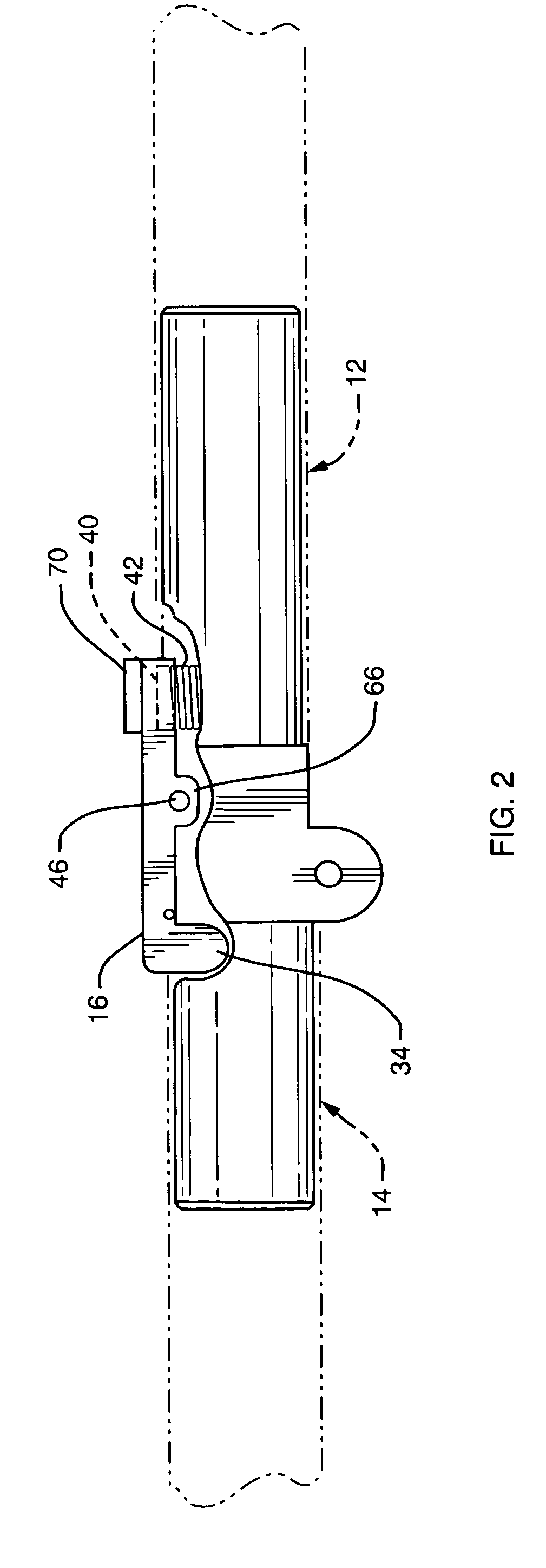
[0012]The invention consists of essentially three main pieces; a self locking latch lever, an axially aligning connection means and a plurality of self locking hinges. Each self locking hinge contains three pieces; two hinge portions that are pivotally joined and a self locking spring loaded latch that locks the two hinge portions together. The two hinge portions are designed to be disposed end to end and are pivotally engaged with each other around a pivot pin. The hinge portions are geometrically designed so that they do not protrude beyond the pole diameter. The only exceptions are the lobe portions of the hinge that create an offset pivot point. The offset pivot point allows the poles attached to the hinge to touch and to be parallel when the entire assembly is in its closed position. The third portion of the hinge is the self locking latch which is spring actuated. The self locking latch is permanently attached to top portion of one hinge portion. The self locking latch locks the hinge by engaging a recess or notch in the opposing hinge portion. When engaged the hinge creates a strong connection that is sufficient for its application purposes.
[0013]Accordingly, one object of this invention is to provide a self locking hinge assembly that can be easily engaged and disengaged with a single hand.
[0014]Another object of this invention is to provide a self locking hinge assembly that can be used in conjunction with a crutch such that the crutch can be folded and unfolded with a single hand, as the same would be a convenience to one using a crutch.
[0015]A third object of this invention is to provide a self locking hinge assembly that is simple and inexpensive to manufacture.

Problems solved by technology

However, none of the prior art has a means of connecting two or more hinges in a poled device to make an effective collapsing hinged device.
But more critically, none of the prior art, individually or collectively, incorporates all of the novel aspects of the present invention of a simple, inexpensive, yet easy to manufacture, strong self locking set of hinges that can be operated with merely a single hand.
The prior art has several different collapsible hinge designs but those designs have a limitation in that the hinge is designed to work solely as an independent hinge.
Other devices have an internal spring loaded means, but have many internal parts that make is complicated and costly to manufacture.
This device fails from the shortcoming of not yielding a true end-to-end 180-degree connection desirable for crutch, walker or other devices.
Furthermore, this hinge device could be disengaged if one where to apply force to underside of the hinge, a concept not desirable for crutches or walkers.
This device does not create a straight 180-degree orientation and does not easily collapse down for easy storage.
All of these references suffer from the common problems of not being able to be engaged or disengaged with a single hand.
Lastly and most critically, all of the abovementioned devices are not designed as multiple hinged assemblies.

Method used


Image

  • Multiple self locking hinge assembly
  • Multiple self locking hinge assembly
  • Multiple self locking hinge assembly

Examples


Embodiment Construction

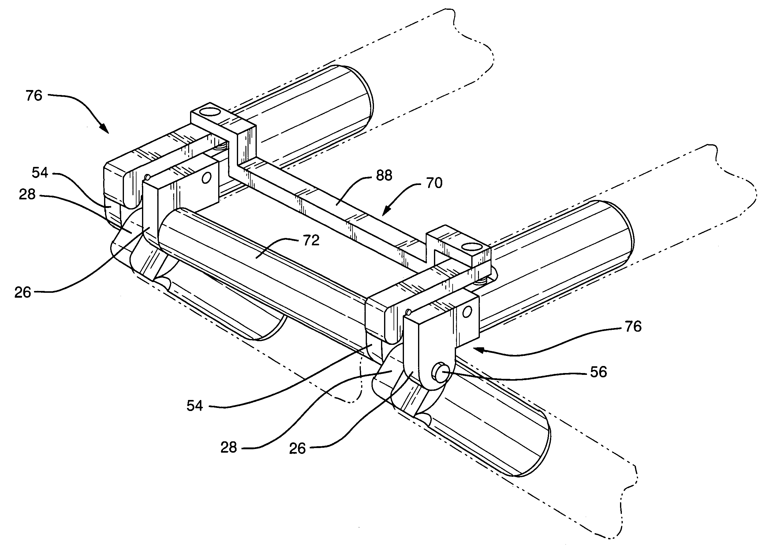
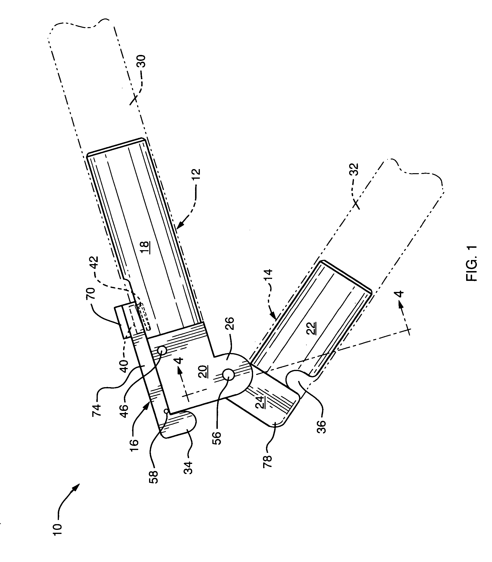
[0029]Referring to the Figures and more specifically FIG. 1 and FIG. 3, the invention 10 consists of essentially three main parts, a lever 70, a connecting device 72 and a plurality of self locking hinges 76. Each self locking hinge 76 itself consists of three main parts, a first hinge portion 12, a second hinge portion 14 and a spring loaded self locking latch 16. Each hinge portion has a main body portion and a connecting portion containing lobes designed to connect the two hinge portions. The first hinge portion 12 has a main body portion 18 and a connecting portion 20 with two lobes 26 and 54. The second hinge portion 14 has a main body portion 22 and a connecting portion 24 with a single lobe 28. The main body portions of the hinge portions are designed to allow the hinge portions to be engaged with poles or other devices. In FIG. 1, the main body portion 18 of first hinge portion 12 is disposed in pole 30 while the main body portion 22 of second hinge portion 14 is disposed in...


PUM


Abstract

The present invention is an ingenuously designed multiple self locking hinge assembly that is simple to manufacture and can come in a variety of shapes and sizes given the application requirements. It has few parts making it cost effect and simple to use. The hinge assembly can easily be opened and closed with a single hand while at the same time creating a strong hinge connection. The invention can be used in a number of applications, including use with multiple poled devices for many common applications such as crutches, walkers, golf bag and baby carriages to name a few. The invention can also be used in conjunction with devices that require a collapsible frame. The invention also provides lateral strength and stability to a multiple poled device.

Description

[0001]This application is a continuation-in-part of a U.S. application, application Ser. No. 10 / 695,693, filed on Oct. 29, 2003 now U.S. Pat. No. 7,003,849.BACKGROUND[0002]a) Field of the Invention[0003]This invention relates to the field of folding hinges designed for use in conjunction with devices that use multiple poles or similar means and where it is desirable to easily erect and collapse the same. More specifically, this device is used in conjunction with crutches where the user typically has an injury, is handicapped or otherwise physically challenged; and as such, would desire the convenience of a single hand operation. The device is also applicable with walkers, golf bag carriages, baby carriages, and similar devices. This invention consists of a plurality of self locking hinges connected via a connection means and a linked release mechanism that provides a means to engage and disengage the invention using only a single hand making use of multiple poled and related devices...

Claims


Application Information

Patent Timeline
Patent Type & Authority Patents(United States)
IPC IPC(8): B25G3/18A45B9/00A63C11/22E05D11/10
CPCA63C11/221E05D11/1007A45B9/00A45B2009/005A63C2203/10Y10T16/5285Y10T403/32409Y10T16/52Y10T16/50Y10T16/498Y10T16/473
Inventor COHEN, ARNOLD H.MALOY, JAMES Q.NEWMAN, LORI R.SMITH, MICHAEL
Owner FULCRUM SPORTS
Learn More