
Selectable length meander line antenna

a technology of meander line and selectable length, which is applied in the direction of loop antenna, resonance antenna, radiating element structure, etc., can solve the problems of increasing the cost and efficiency of tuning circuitry, and the overall efficiency may drop at frequencies that are not within the optimal tuning range, so as to achieve the effect of simple (and convenient) operation

Inactive Publication Date: 2006-10-31
CENTURION WIRELESS TECH INC
View PDF4 Cites 30 Cited by
  • Summary
  • Abstract
  • Description
  • Claims
  • Application Information

AI Technical Summary

Benefits of technology

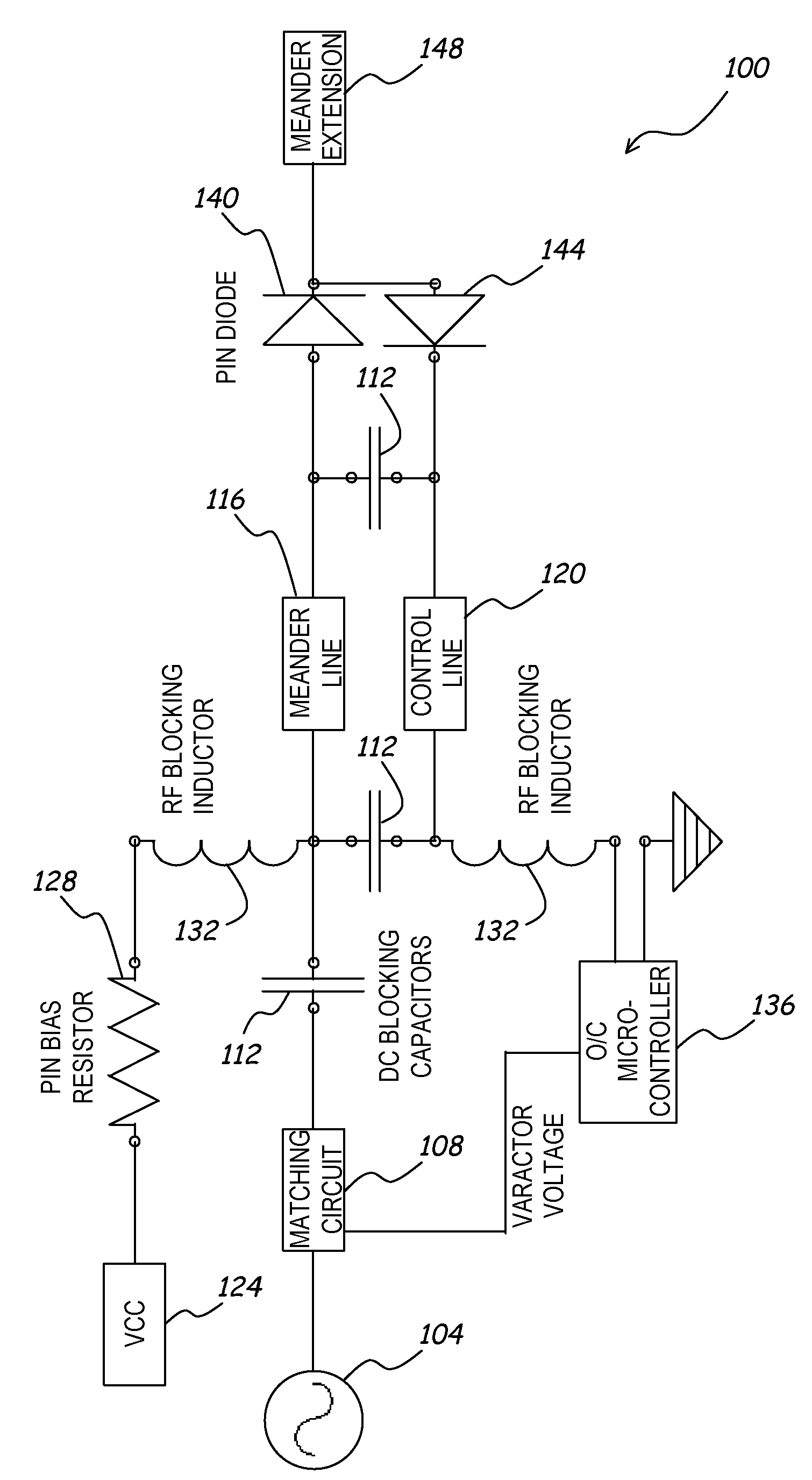
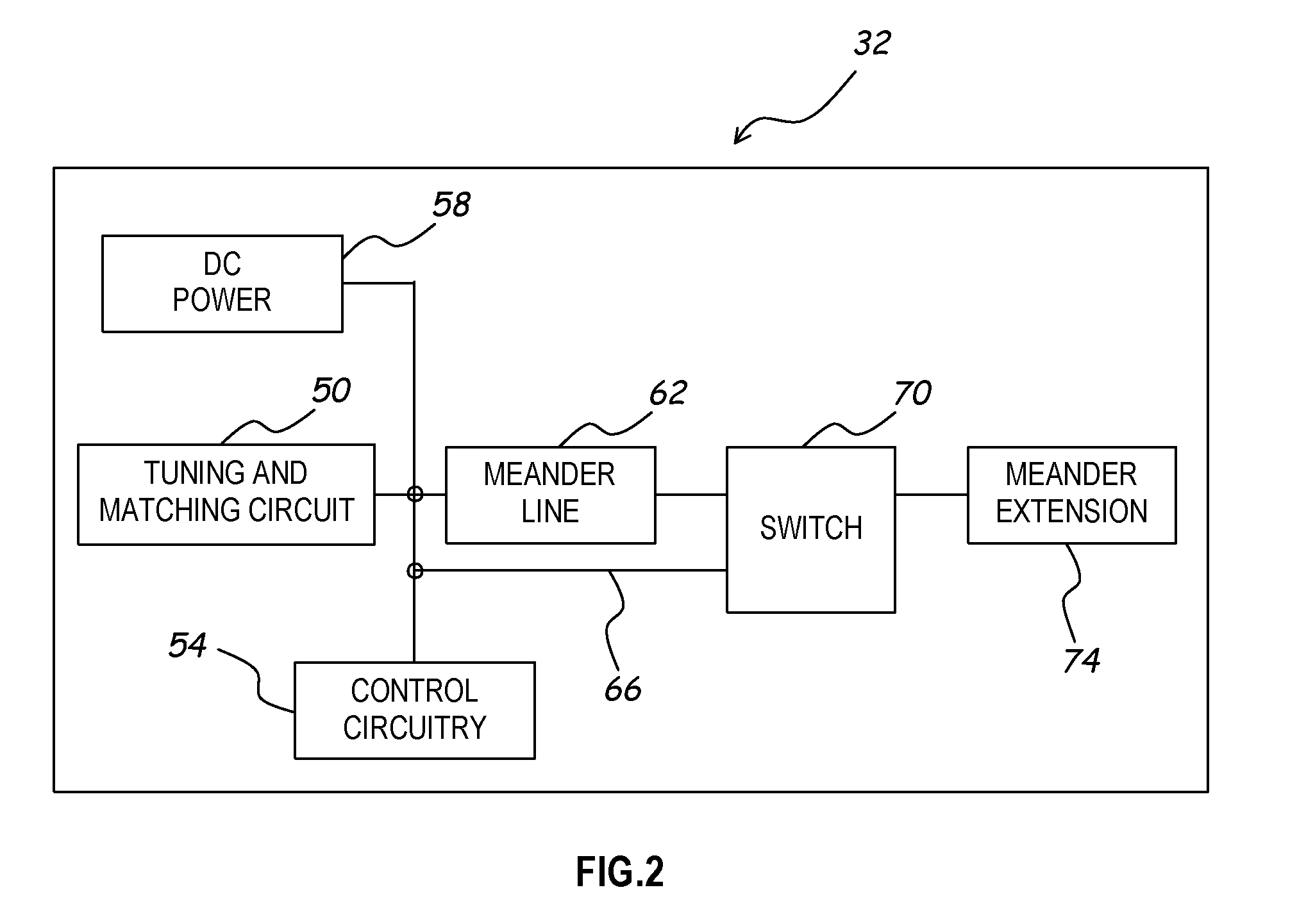
"The present invention provides a compact antenna system that can tune RF signals over a wide range of frequencies using a simple tuning circuit. The antenna has a selectable length, which allows for different center frequencies depending on the desired application. The tuning circuitry can tune the antenna to a range of frequencies around the center frequency. A control line is used to switch the length of the antenna, which is connected to the antenna at the same RF frequencies throughout the range of frequencies required for operation. The system includes a first and second meander line antenna portions, which can be connected together using a switch element to change the center frequency and range of operation. The switch element can be a PIN diode, a MEMS device, or a relay. The system also includes a second control line and a third meander line antenna portion for added flexibility. The technical effects of this invention include a compact, versatile antenna system that can easily tune RF signals for different applications."

Problems solved by technology

As frequency ranges increase, the cost and efficiency of the tuning circuitry also increases.
Furthermore, the overall efficiency may drop at frequencies that are not within an optimum tuning range of the antenna.

Method used


Image

  • Selectable length meander line antenna
  • Selectable length meander line antenna
  • Selectable length meander line antenna

Examples


Embodiment Construction

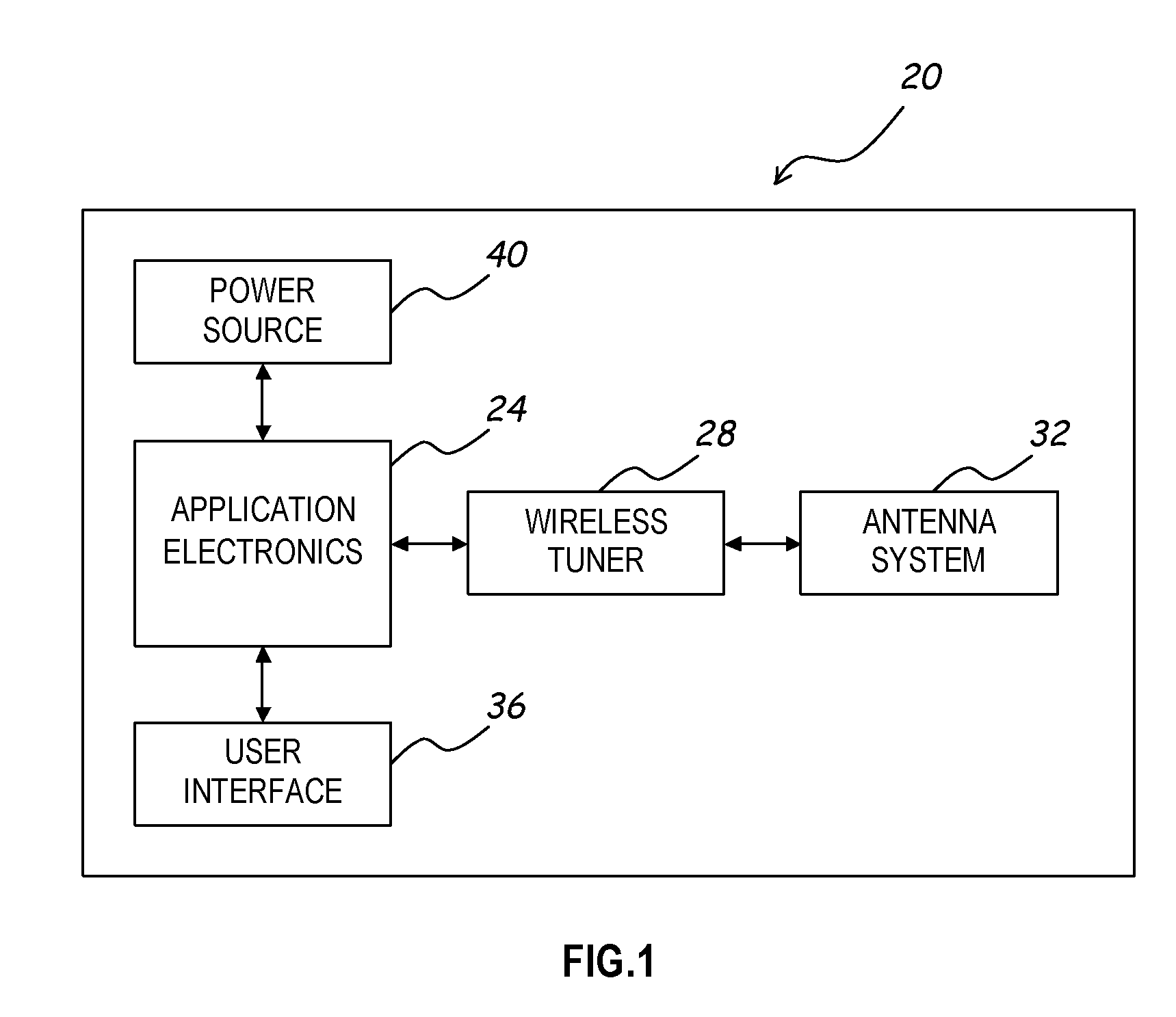
[0012]The present invention recognizes that antennas are designed having a center frequency at which the antenna may be tuned with relatively little requirements for tuning and matching circuitry. The antennas include tuning and matching circuitry that are capable of adjusting the antenna properties to tune frequencies over a specified frequency range relative to the center frequency. As this frequency range increases, the complexity (and thus cost) of the tuning and matching circuitry increases, and the efficiency of the antenna may decrease. The present invention thus provides an antenna element with a switchable extension that may be used to change the size of the radiating surface and provide an antenna that has two or more separate center frequencies. Thus, the range of frequencies that may be tuned by the antenna is enhanced, while maintaining relatively low complexity tuning and matching circuitry. Switching for the extension is performed by a switching element that is locate...


PUM


Abstract

A single antenna element with a switchable extension may be used to change the size of the radiating surface and provide an antenna that has two or more separate center frequencies. The range of frequencies that may be tuned by the antenna is enhanced, while maintaining relatively low complexity tuning and matching circuitry. Switching for the extension is performed by a switching element that is located at the point of connection of the extension to the antenna element. A control line supplies a control signal to the switching element to enable and disable the extension. The control line is positioned in close proximity to the antenna element to enhance coupling between the antenna element and the control line.

Description

FIELD OF THE INVENTION[0001]The present invention is directed to antennas capable of tuning over a large frequency range, and, more specifically, to an antenna with a selectable radiating surface area.BACKGROUND OF THE INVENTION[0002]Many present day analog and digital devices are capable of receiving and / or transmitting radio frequency (RF) signals. Such devices include, for example, radios, computers, video games, televisions, and wireless telephones. A large of number of these devices are required to tune over many different frequencies with a single antenna in order to operate as required by the particular application. For example, a wireless telephone may need to operate over several different frequency bands in order to tune signals on the different bands, such as a GSM band and an analog band.[0003]As is understood, such systems require antennas having tuning circuitry in order to tune the device to the proper frequency. As frequency ranges increase, the cost and efficiency o...

Claims


Application Information

Patent Timeline
Patent Type & Authority Patents(United States)
IPC IPC(8): H01Q1/38H01Q1/36H01Q1/50H01Q3/24H01Q7/00
CPCH01Q1/38H01Q9/14
Inventor WINTER, JAMES BLAKE
Owner CENTURION WIRELESS TECH INC
Learn More