
Coaxial cable connector

a technology of coaxial cable and connector, which is applied in the direction of connections, basic electric elements, electric devices, etc., can solve the problems of poor connectivity and achieve the effect of simple assembly and simplified structur

Active Publication Date: 2006-10-24
EZCONN
View PDF9 Cites 131 Cited by
  • Summary
  • Abstract
  • Description
  • Claims
  • Application Information

AI Technical Summary

Benefits of technology

[0005]It is a main object of the present invention to disclose a coaxial cable connector with simplified structure and simple assembly.

Problems solved by technology

If the force is applied carelessly, the poor connectivity is caused.

Method used


Image

  • Coaxial cable connector
  • Coaxial cable connector
  • Coaxial cable connector

Examples


Embodiment Construction

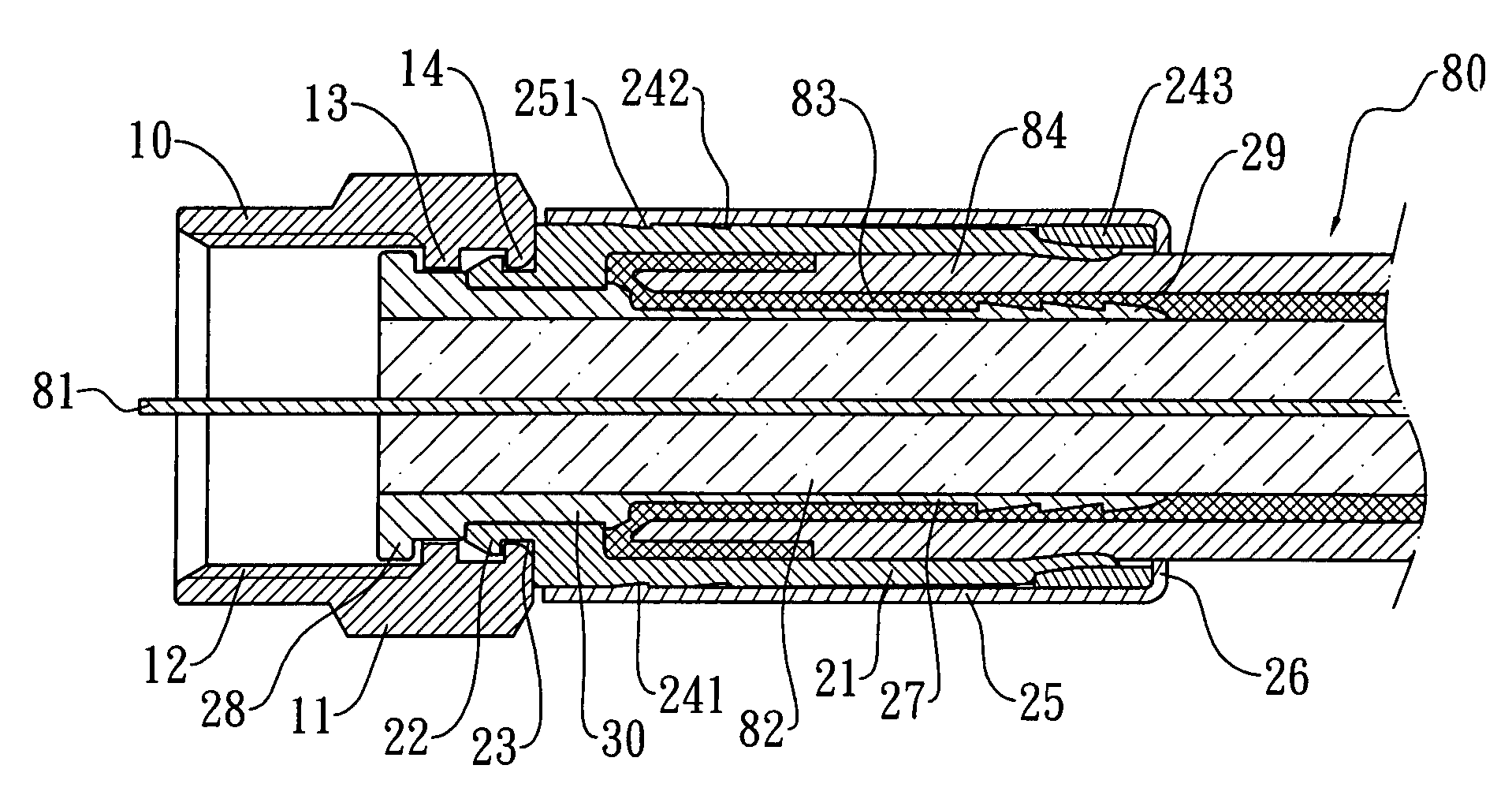
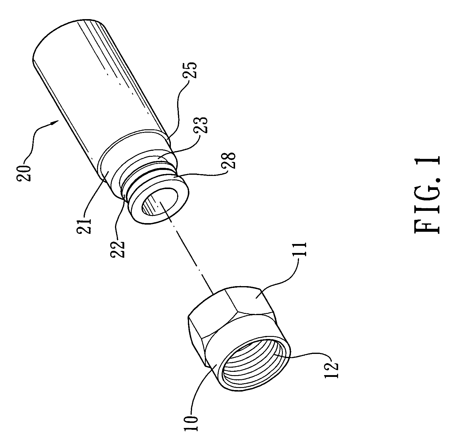
[0013]Referring to FIG. 1 and FIG. 2, a coaxial cable connector of the present invention comprises a head 10 and a hollow cylinder 20. In this preferred embodiment, a F type connector is illustrated. The head 10 of the F type connector has a hexagonal body 11 at its one end and a stopper 14 on the inside of the hexagonal body 11. The head 10 further has a plurality of internal screw threads 12 and a flange 13 around its inner surface.

[0014]The hollow cylinder 20 comprises an elastic cylinder 21, a tubular shaft 27, and a protective cylinder 25. A bended part is formed at one end of the inner edge of the elastic cylinder 21, wherein a trench 23 and a hook 22 are circularly formed at this end of the outside of the elastic cylinder 21. A notch 24 is circularly formed near the other end of the elastic cylinder 21 so as to define a locking ring 243 on the elastic cylinder 21 behind the notch 24. Besides, two recesses 241 and 242 are formed in proper positions in front of the notch 24. A ...


PUM


Abstract

A coaxial cable connector comprises a head and a hollow cylinder. The hollow cylinder comprises a protective cylinder, a tubular shaft, and an elastic cylinder. The tubular shaft comprises a guide hole, a plurality of ladders, a locking flange, and a plurality of hooks. The elastic cylinder comprises a trench and a hook at one end and a locking ring defined by a notch near the other end. A bended metal tube having a stopper is mounted on the protective cylinder. In the coupling process, the coaxial cable inserts into the hollow cylinder. By using a pressure from a tool to break the notch of the elastic cylinder, the locking ring is separable from the elastic ring, and the locking ring shifts forward continuously along an inclined surface of the notch. Since the protective cylinder restrains the locking ring, the connector can couple with the coaxial cable tightly by pressing down the locking ring.

Description

FIELD OF THE INVENTION[0001]The present invention relates to a coaxial cable connector for enhancing the connection stability between the connector and the coaxial cable, and more particularly to a connector suitable to a wire such as coaxial cable or the like for use in signal transmission.BACKGROUND OF THE INVENTION[0002]In general cable TV system and common antenna TV system, the coaxial cable is spread to a splitter through a main line, and the coaxial cable is then further spread from the splitter to clients through secondary lines. As a result, the clients are capable of receiving signals from the TV system. The main line is connected to the splitter through a coaxial cable connector, which is mounted on the tail of the coaxial cable.[0003]As shown in FIG. 5, the conventional coaxial cable connector such as a F type coaxial cable connector includes a main body A, wherein the main body A further includes a clamping tube A1, a pillar B coaxially located in the clamping tube A1, ...

Claims


Application Information

Patent Timeline
Patent Type & Authority Patents(United States)
IPC IPC(8): H01R9/05
CPCH01R9/0518
Inventor LIN, HSIU-YEN
Owner EZCONN
Learn More