Fluid dynamic bearing motor

a dynamic bearing and motor technology, applied in sliding contact bearings, instruments, record information storage, etc., can solve the problems of oil leakage, inability to perform simultaneous and effective prevention of oil leakage, and inability to improve load support force, so as to prevent oil leakage and improve the structure of the oil groove

Inactive Publication Date: 2006-10-24
G&W TECH
View PDF2 Cites 11 Cited by
  • Summary
  • Abstract
  • Description
  • Claims
  • Application Information

AI Technical Summary

Benefits of technology

[0015]To solve the above and / or other problems, the present invention provides a fluid dynamic bearing motor in which the structure of an oil groove is improved so that a load support force of a rotor is improved and simultaneously leakage of oil is prevented.
[0016]The present invention provides a fluid dynamic bearing motor having an improved oil groove which can reduce leakage of oil due to high internal pressure of a fluid dynamic bearing portion during the operation of the motor.

Problems solved by technology

First, the oil groove 22 of the fluid dynamic bearing simultaneously performs functions of supporting a load of the rotor and preventing leakage of the oil, by increasing the pressure of the oil during the rotation of the rotor. To increase the load support force, it is advantageous to increase an angle A of the oil groove 22 in view of the dynamics. In contrast, to prevent leakage of the oil, it is advantageous to decrease the angle A. However, since the oil groove 22 is typically formed at a predetermined angle, the improvement of the load support force and the prevention of leakage of the oil cannot be performed simultaneously and effectively.
Second, as shown in FIG. 2, since the direction of flow of the oil in the oil gap and an end portion 22a of the oil groove 22 is parallel to the direction of rotation of the shaft 40, an area whose pressure (negative pressure) is less than the atmospheric pressure is formed narrow in the end portion area of the oil groove 22. As a result, the oil leaks due to high internal pressure in the oil gap.

Method used


Image

  • Fluid dynamic bearing motor
  • Fluid dynamic bearing motor
  • Fluid dynamic bearing motor

Examples


Embodiment Construction

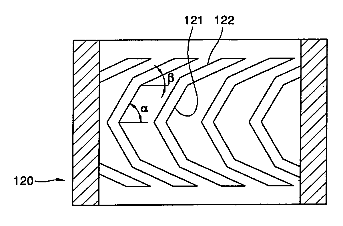
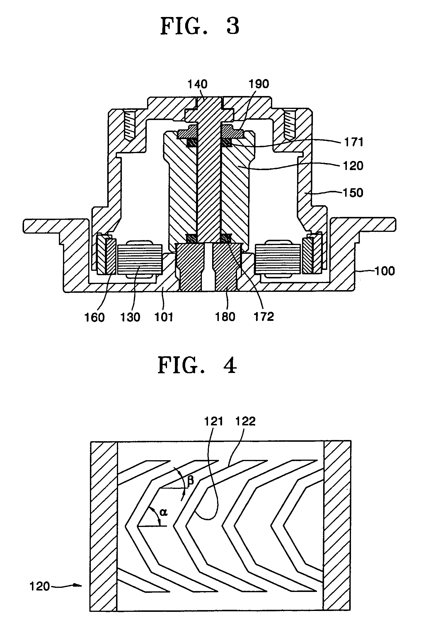
[0025]Referring to FIG. 3, a fluid dynamic bearing motor according to an embodiment of the present invention has a structure in which a rotor rotating with respect to a stator is supported by a fluid dynamic bearing.

[0026]The stator includes a housing 100, a sleeve 120 fixed at a center portion of the housing 100 and having a shaft hole formed at the center portion thereof, and a core 130 fixed to a portion around the center portion of the housing 100 and having a coil wound therearound.

[0027]The rotor includes a shaft 140 coupled to the shaft hole capable of rotating while forming an oil gap and a hub 150 fixed to an upper end portion of the shaft 140 and having a magnet 160 attached to an inner circumferential surface of the hub 150 and generating an electromagnetic force by an interaction with the core 130.

[0028]Upper and lower thrust plates 171 and 172 are circular and coupled to the upper and lower portions of the shaft 140, respectively, and form fluid dynamic pressure with th...


PUM

PropertyMeasurementUnit
angleaaaaaaaaaa
angleaaaaaaaaaa
angleaaaaaaaaaa

Abstract

Provided is a fluid dynamic bearing motor in which a rotor is rotatably supported by forming an oil gap between the rotor and a stator to form a fluid dynamic pressure bearing and a plurality of oil grooves are formed in a surface of the rotor or stator forming the oil gap and facing each other. The oil grooves include a first oil groove inclined at a first angle with respect to a circumferential direction, and a second oil groove extending from an end portion of the first oil groove and inclined at a second angle with respect to the circumferential direction. The first angle is formed relatively greater than the second angle.

Description

BACKGROUND OF THE INVENTION[0001]This application claims the priority of Korean Patent Application No. 2003-78041, filed on Nov. 5, 2003, in the Korean Intellectual Property Office, the disclosure of which is incorporated herein in its entirety by reference.[0002]1. Field of the Invention[0003]The present invention relates to a fluid dynamic bearing motor, and more particularly, to a fluid dynamic bearing motor which can improve a load support force of a fluid dynamic bearing and effectively prevent leakage of oil.[0004]2. Description of the Related Art[0005]A fluid dynamic bearing motor typically has an oil gap formed between a rotor and a stator of the motor. The oil gap is filled with oil having a predetermined viscosity and the oil is compressed as the rotor rotates so that fluid dynamic pressure is generated to rotatably support the rotor. Also, to increase the fluid dynamic pressure, an oil groove is formed in surfaces of the rotor and the stator forming the oil gap and facing...

Claims


Application Information

Patent Timeline
Patent Type & Authority Patents(United States)
IPC IPC(8): F16C17/02F16C33/10H02K5/16G11B19/20
CPCF16C17/026F16C33/107G11B19/2009F16C2370/12H02K5/16
Inventor KIM, SANG UK
Owner G&W TECH
Why Eureka
Try Eureka