
Method of determining and indicating airbag suppression status

a technology of airbag suppression and status, applied in the direction of pedestrian/occupant safety arrangement, instruments, tractors, etc., can solve the problems of annoyance of occupants, suppression status fluctuation, and undermine the confidence of occupants in the suppression system, so as to achieve effective increase the separation

Active Publication Date: 2006-10-10
APTIV TECH LTD
View PDF8 Cites 6 Cited by
  • Summary
  • Abstract
  • Description
  • Claims
  • Application Information

AI Technical Summary

Benefits of technology

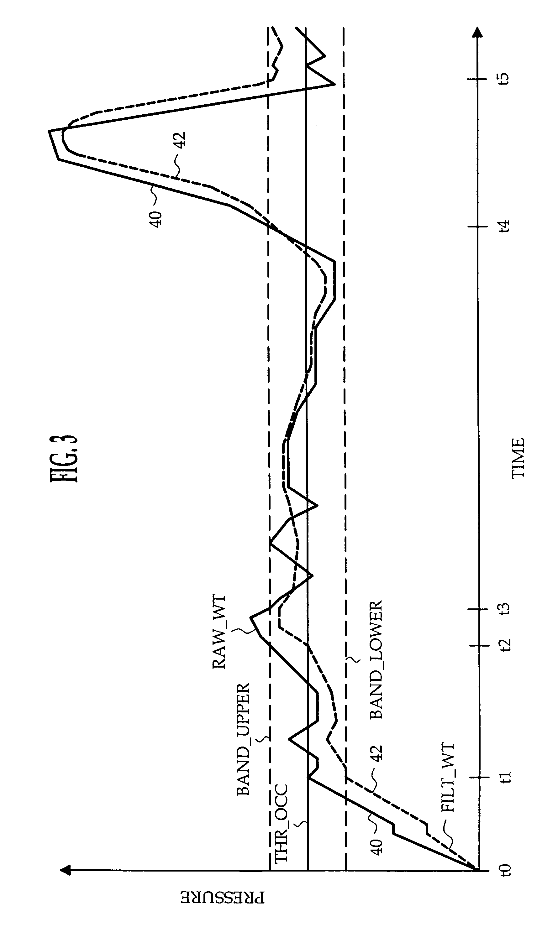
[0004]The present invention is directed to an improved method of determining and indicating airbag suppression status in an occupant weight-based airbag suppression system. The suppression status is determined by low-pass filtering the measured or raw occupant weight with an adjustable time constant filter and comparing the filtered weight to one or more threshold values. The filter time constant is ordinarily set to a first value that provides relatively fast tracking of the raw occupant weight, but is set to a second value that provides relatively slow tracking of the raw occupant weight when both the raw and filtered occupant weights are within a specified band about the threshold value. In a preferred implementation, the threshold value and band are dynamically adjusted after the suppression status is initially determined so as to effectively increase the separation between the filtered weight and the threshold.

Problems solved by technology

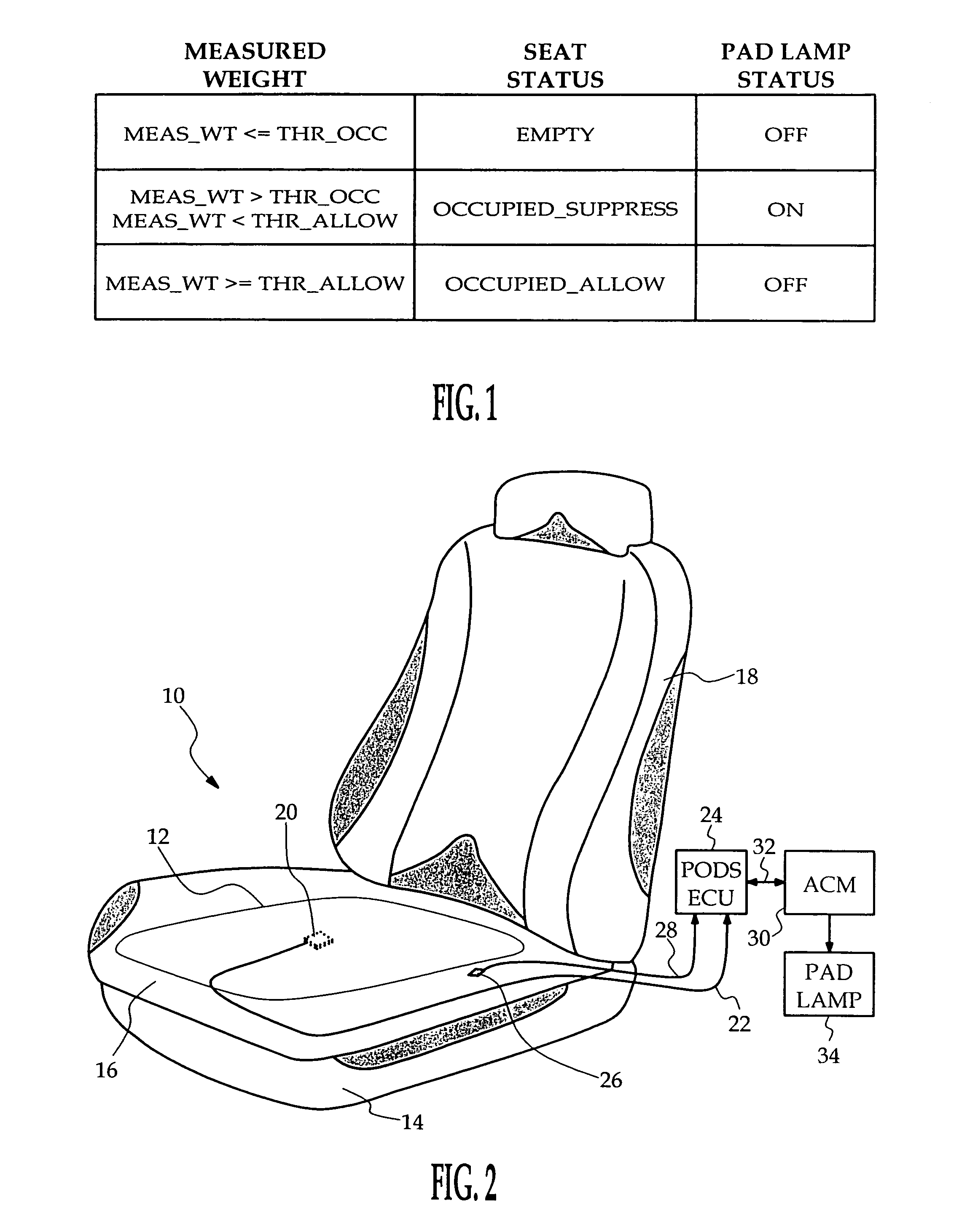
In any event, the measured weight of an occupant (or an inanimate object for that matter) tends to vary somewhat due to occupant weight shifting and vehicle movement, resulting in oscillation of the suppression status, particularly if MEAS_WT is close to THR_OCC or THR_ALLOW.
Such oscillation is undesired of course, and the accompanying oscillation or toggling of the PAD lamp tends to annoy the occupants and undermine their confidence in the suppression system.
While hysteresis can be employed to prevent repeated changes in the occupant status due to minor oscillation of the measured weight, experience has shown that hysteresis alone is inadequate.

Method used


Image

  • Method of determining and indicating airbag suppression status
  • Method of determining and indicating airbag suppression status
  • Method of determining and indicating airbag suppression status

Examples


Embodiment Construction

[0010]The present invention is disclosed in the context of a restraint system for an occupant of a vehicle passenger seat, where the occupant seated weight is detected based on the fluid pressure in a seat cushion bladder. In general, however, the present invention applies to other types of weight-based occupant detection systems as well, such as systems that sense the strain in a seat frame element, or systems that include a network of pressure sensitive cells distributed over the seating area.

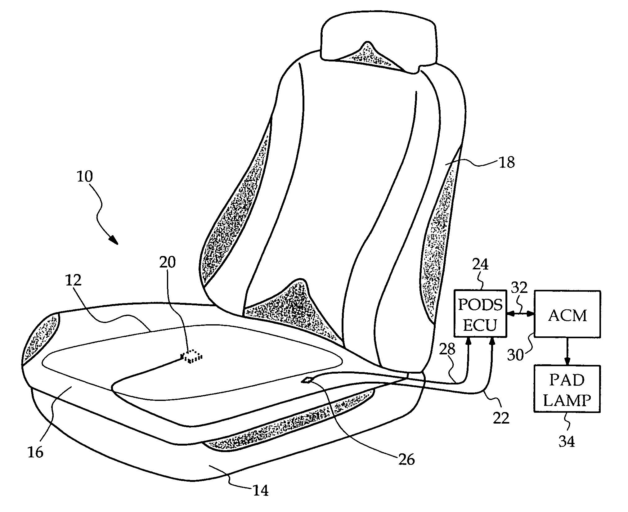
[0011]Referring to FIG. 2, the vehicle seat 10 is supported on a frame 14, and includes foam cushions 16 and 18 on the seat bottom and back. The bladder 12 is disposed in or under the foam cushion 16 substantially parallel with the central seating surface, and preferably contains a fluid such as silicone which is non-corrosive, and not subject to freezing at extreme ambient temperatures. In addition, semi-rigid interface panels may be placed above and / or beneath the bladder 12 to protect the ...


PUM


Abstract

An occupant weight-based airbag suppression method utilizes adjustable time constant filtering and dynamic threshold adjustment to reliably determine and indicate airbag suppression status. The filter time constant is ordinarily set to a first value that provides relatively fast tracking of the raw occupant weight, but is set to a second value that provides relatively slow tracking of the raw occupant weight when both the raw and filtered occupant weights are within a specified band about the threshold value. The threshold value and band are dynamically adjusted after the suppression status is initially determined so as to effectively increase the separation between the filtered weight and the threshold.

Description

TECHNICAL FIELD[0001]This invention relates to airbag deployment suppression in a motor vehicle based on detected occupant weight, and more particularly to a method of determining and indicating the airbag suppression status.BACKGROUND OF THE INVENTION[0002]Vehicle occupant seated weight detection systems are useful in connection with air bags and other pyrotechnically deployed restraints as a means of characterizing the occupant and determining if airbag deployment should be disabled. In particular, the seated weight of the occupant may be used to distinguish between large and small occupants, and between a small occupant and an empty seat. For example, a large occupant is deemed to be present if the measured seated weight (MEAS_WT) is above an “allow” threshold (THR_ALLOW) corresponding to a minimum large occupant seated weight such as 60 lbs; a small occupant is deemed to be present if MEAS_WT is between THR_ALLOW and an “occupied” threshold (THR_OCC) corresponding to a minimum s...

Claims


Application Information

Patent Timeline
Patent Type & Authority Patents(United States)
IPC IPC(8): G01G9/00B60R21/01B60R21/015
CPCB60R21/01516
Inventor GRAY, CHARLES A.RENNAKER, ROYCE L.HAYDEN, ERIC C.SCALES, CHANCE LSCOTT, JOHN D.COSGROVE, BRENDA S.
Owner APTIV TECH LTD
Learn More