
Power source for sensors

a technology for power sources and sensors, applied in the direction of electrical equipment, electrical generator control, combustion process, etc., can solve the problems of high installation cost of wiring to connect sensors to power outlets, limited power supply of each of the above listed sources, and inability to direct sunligh

Inactive Publication Date: 2006-09-26
AVAGO TECH WIRELESS IP SINGAPORE PTE
View PDF16 Cites 39 Cited by
  • Summary
  • Abstract
  • Description
  • Claims
  • Application Information

AI Technical Summary

Benefits of technology

"The present invention is about a sensor that can be placed in a pipe to monitor fluid flow. The sensor is powered by scavenging power from the fluid flow. This technology allows for efficient and effective monitoring of fluid flow in a wireless way."

Problems solved by technology

However, each of the above listed sources of power has limitations.
For example, for some sensors, no direct pathway to sunlight is available.
The wiring required to connect a sensor to a power outlet may be expensive to install.
This can present a difficulty when the sensor is not readily accessible.
Even when the sensor is accessible, it is often difficult to detect when a battery is discharged.
The necessary monitoring of the condition of the battery can be inconvenient and therefore neglected.

Method used


Image

  • Power source for sensors
  • Power source for sensors
  • Power source for sensors

Examples


Embodiment Construction

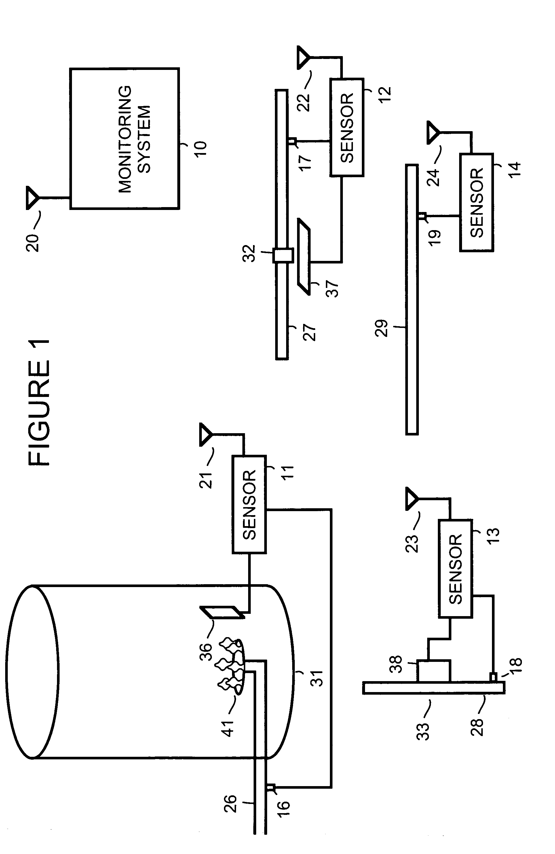
[0010]FIG. 1 is a simplified block diagram showing a monitoring system 10 in wireless communication with a sensor 11, a sensor 12, a sensor 13 and a sensor 14. For example, sensor 11 transmits wireless transmissions, via an antenna 21, that are received by an antenna 20 of monitoring system 10. Sensor 12 transmits wireless transmissions, via an antenna 22, that are received by antenna 20 of monitoring system 10. Sensor 13 transmits wireless transmissions, via an antenna 23, that are received by antenna 20 of monitoring system 10. Sensor 14 transmits wireless transmissions, via an antenna 24, that are received by antenna 20 of monitoring system 10.

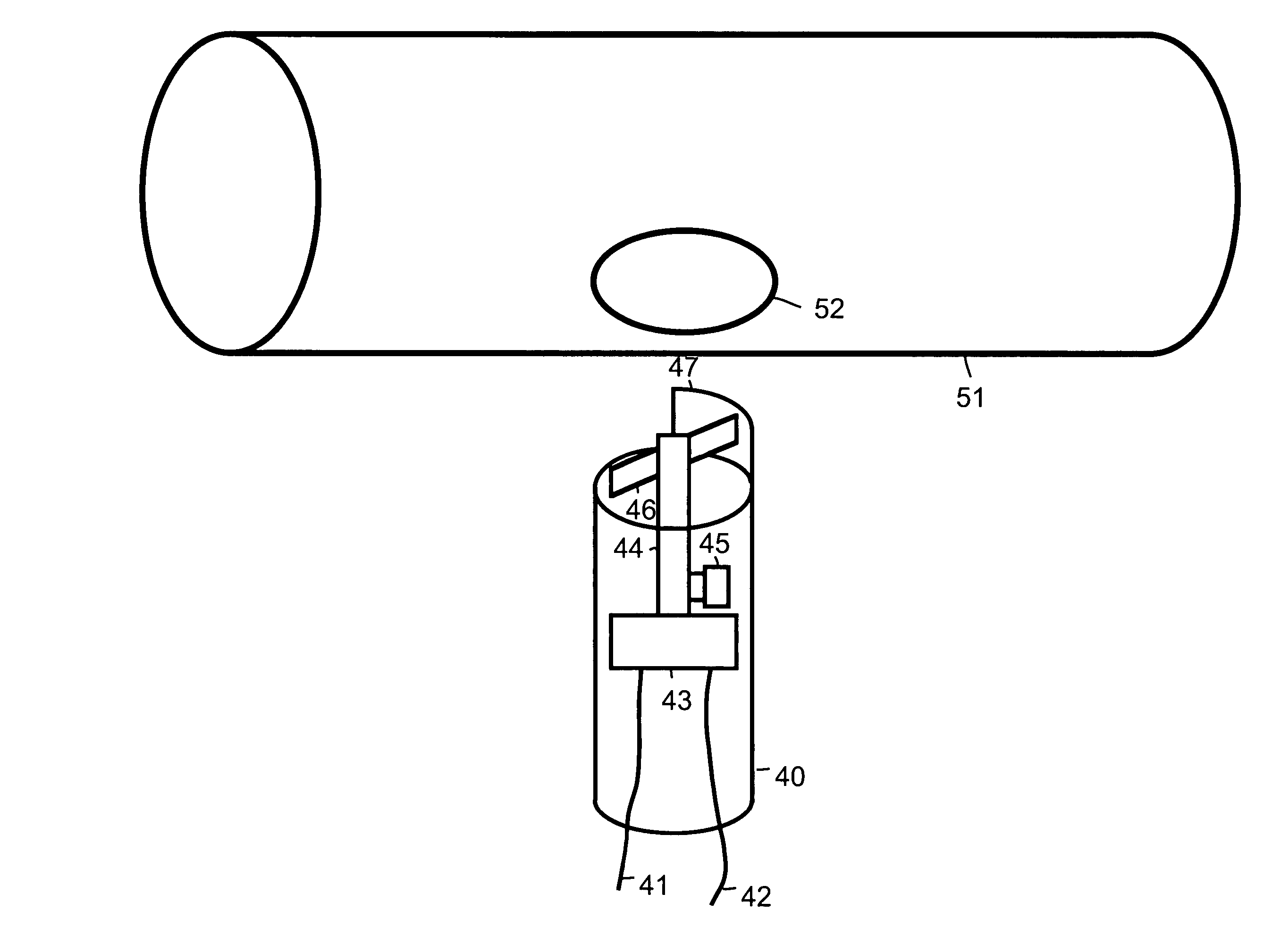
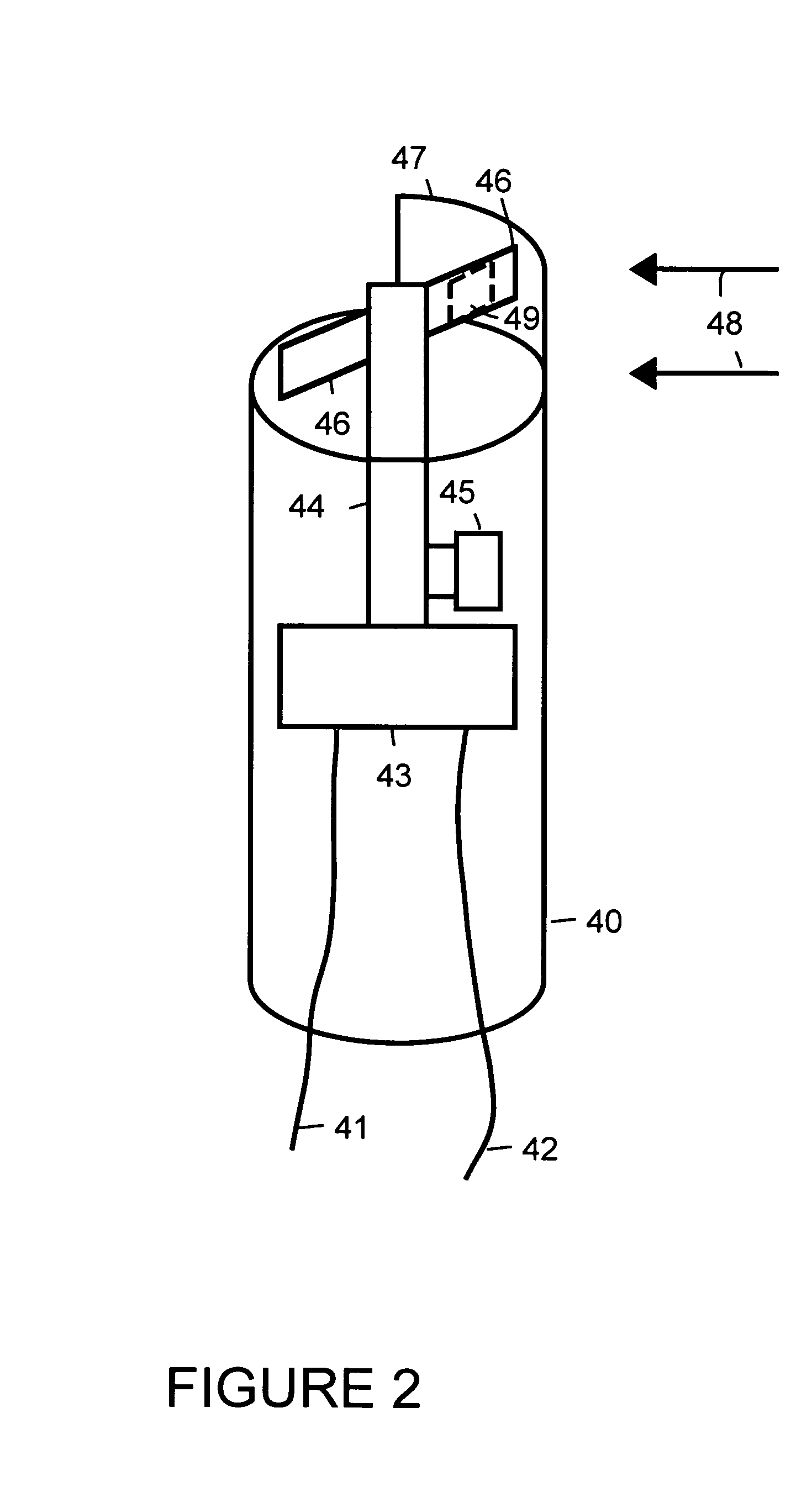
[0011]Sensor 11 uses an imager 36 to monitor a flame 41 within an appliance 31. For example, appliance 31 is a furnace, water heater, dryer or some other appliance that uses a gas to produce a flame. Sensor 11 scavenges power from fluid flow within a pipe 26 used to supply gas for flame 41. Power is scavenged through use of a generator 16.

[...


PUM


Abstract

A sensor is placed in wireless communication with a monitoring system. Power for the sensor is generated by scavenging power from fluid flow within a pipe.

Description

BACKGROUND[0001]There is an increasing recognition of the usefulness of sensors to monitor the condition of property and the operation of appliances. Typically, power outlets or batteries are used to provide power for sensors. In some instances, where sunlight is available, solar power may be also utilized.[0002]However, each of the above listed sources of power has limitations. For example, for some sensors, no direct pathway to sunlight is available. The wiring required to connect a sensor to a power outlet may be expensive to install. Batteries often discharge after a period of time and need to be replaced. This can present a difficulty when the sensor is not readily accessible. Even when the sensor is accessible, it is often difficult to detect when a battery is discharged. The necessary monitoring of the condition of the battery can be inconvenient and therefore neglected.[0003]It is desirable, therefore, to explore other potential power sources for sensors.SUMMARY OF THE INVEN...

Claims


Application Information

Patent Timeline
Patent Type & Authority Patents(United States)
IPC IPC(8): F03B13/00H02P9/04
CPCF23N5/187F05B2220/602F23N2005/185F23N2005/181
Inventor MAHOWALD, PETER H.
Owner AVAGO TECH WIRELESS IP SINGAPORE PTE
Learn More