
Turntable with vertically adjustable platter

a technology of turning tables and platters, which is applied in the field of turning tables, can solve the problems of uneven wear on the inner walls of grooves, difficulty in setting the tone arm and cartridge of the turntable, and inconvenient adjustment of the vta used for a particular record, and achieves the effect of easy adjustmen

Inactive Publication Date: 2006-09-12
CALAIO SALVATORE J
View PDF22 Cites 2 Cited by
  • Summary
  • Abstract
  • Description
  • Claims
  • Application Information

AI Technical Summary

Problems solved by technology

Unfortunately, it is very difficult to set the tone arm and cartridge of the turntable to achieve the exact stylus geometry with respect to the record to match that of the cutting lathe when the groove was cut.
Unless countered by anti-skating, this force can cause uneven wear on the inner walls of the grooves.
A number of difficulties are associated with the setting of the VTA.
Foremost, there is no convenient way of knowing what VTA was used when a particular record was cut.
Therefore, visibly setting the arm tube of the tone arm to be parallel with the record surface does not necessarily guarantee the proper or ideal VTA.
Since the VTA cutting angle and the thickness of the vinyl may vary from record to record, the VTA that sounds good for one record may not necessarily sound good for another record.
These constant adjustments, however, are not only bothersome, but they may cause the other adjustments mentioned above to become out of their ideal settings.
Obtaining and maintaining the proper VTA and other tone arm adjustments for turntables is therefore very challenging for many audiophiles.

Method used


Image

  • Turntable with vertically adjustable platter
  • Turntable with vertically adjustable platter
  • Turntable with vertically adjustable platter

Examples


Embodiment Construction

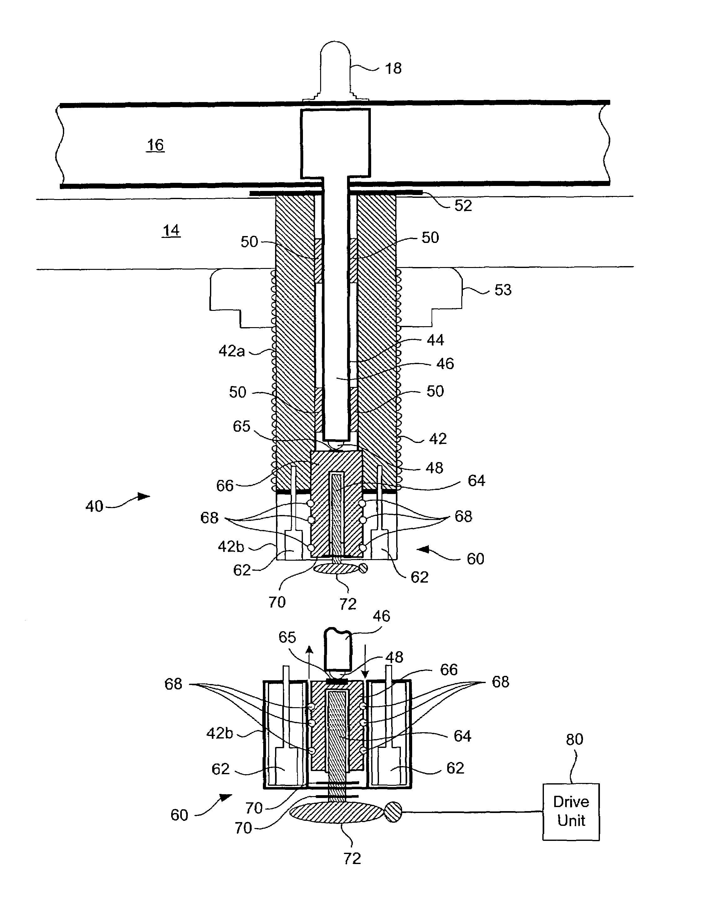
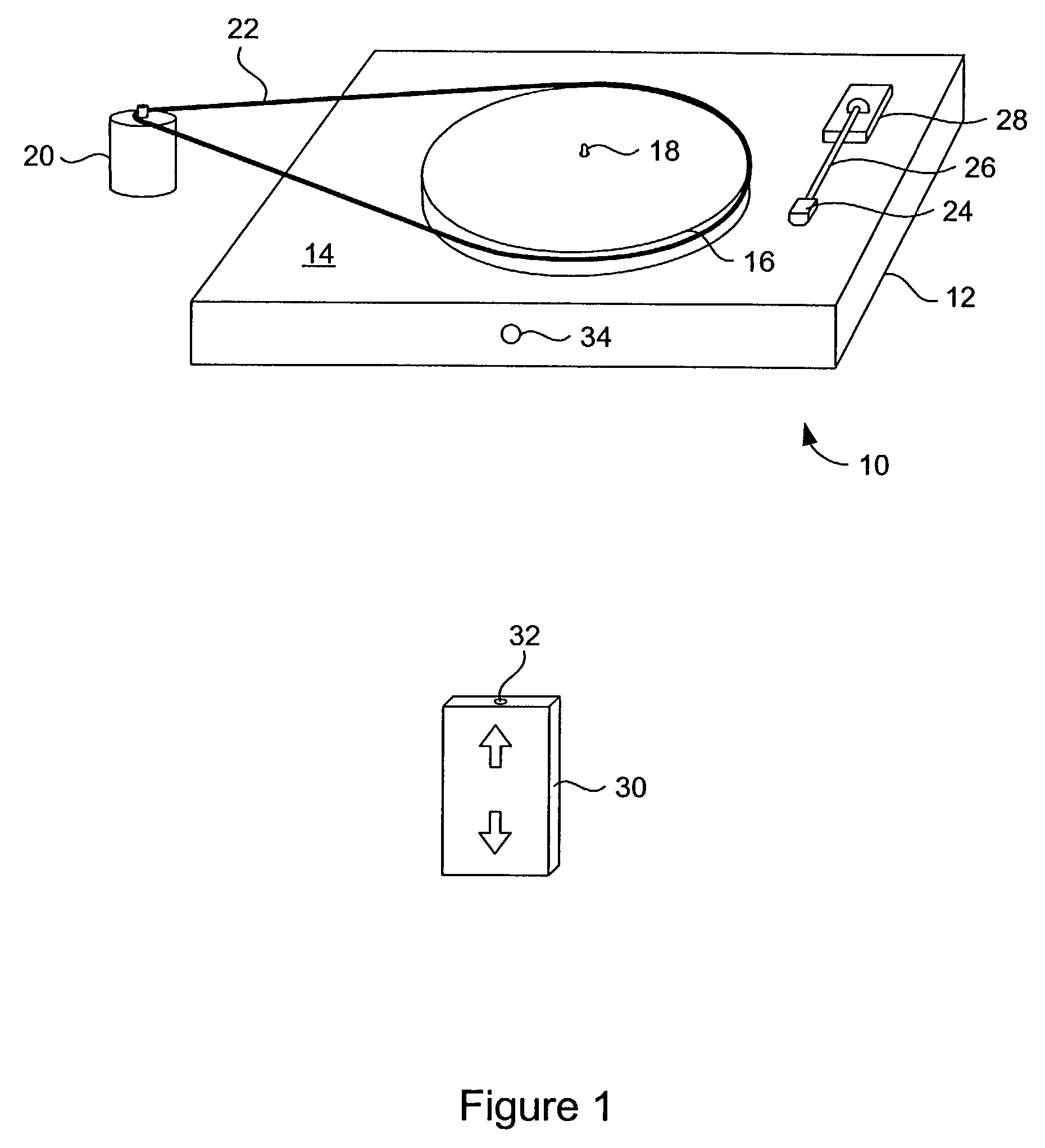
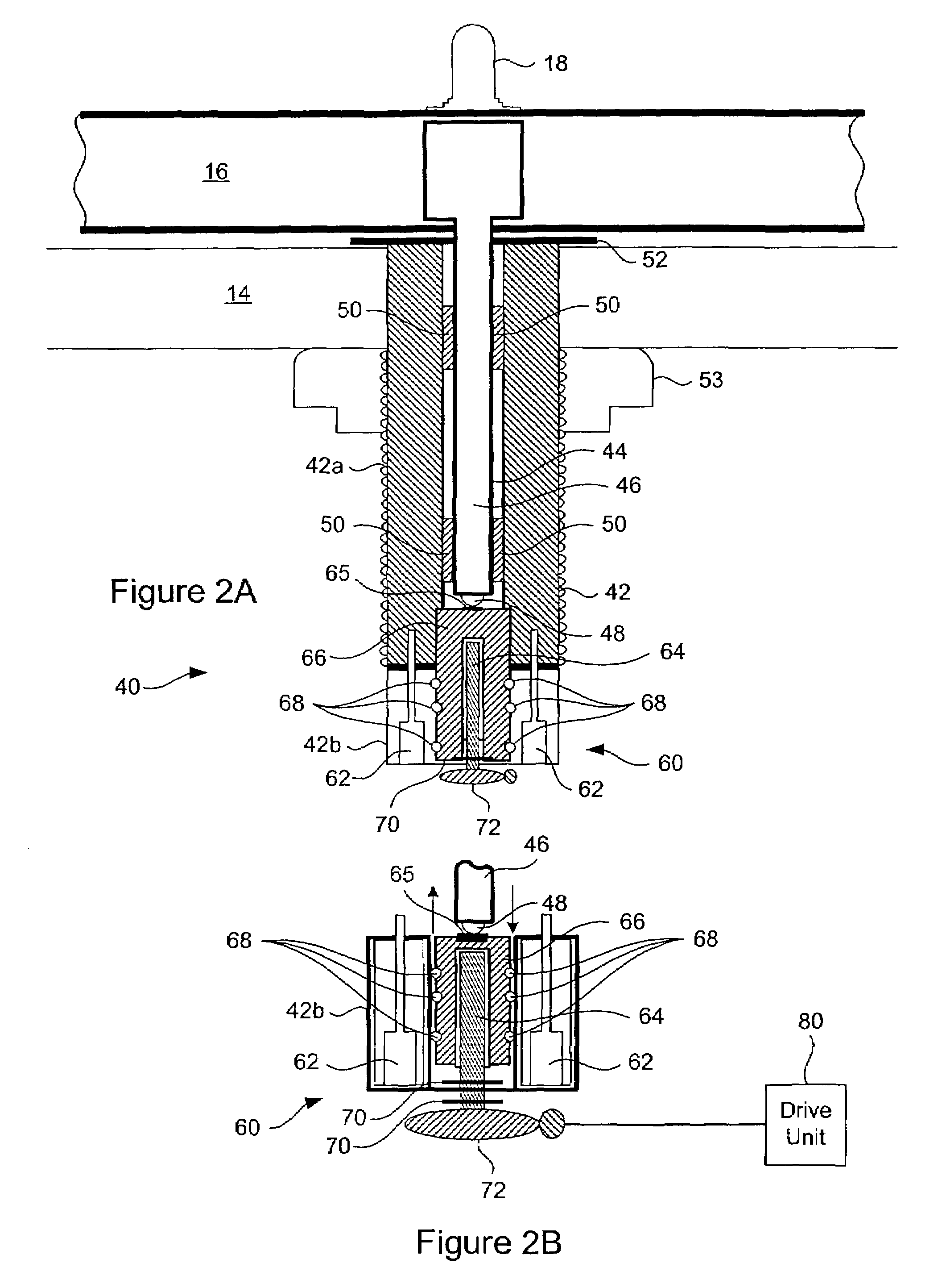
[0019]Referring to FIG. 1, a diagram of a turntable with a vertically adjustable platter and a remote control unit for controlling the height of the platter according to the present invention is shown. The turntable 10 includes a base 12, a plinth 14 formed on the top surface of the base 12, a platter 16, a pin 18 to position a record on the platter, a motor 20, a belt 22 wrapped around the platter 16 and the motor 18, a cartridge 24 connected to a tone arm 26 and an arm board 28 to mount the tone arm 26 onto the plinth 14. The motor 20 and belt 22 are configured to rotate the platter 16. According to various embodiments of the invention, the motor is capable of rotating the platter at 33, 45 or 78 revolutions per minute.

[0020]The platter 16 is configured to rotate about a spindle (not shown) that is housed within the base 12 underneath the plinth 14. The platter 16 is also configured to be vertically positioned so that the Vertical Tracking Angle (VTA) between the stylus of the car...


PUM

PropertyMeasurementUnit
angleaaaaaaaaaa
thickaaaaaaaaaa
heightaaaaaaaaaa

Abstract

A turntable that has a platter that can be vertically positioned so that the VTA between the stylus of the cartridge and the record can be easily adjusted without tweaking or touching the tone arm. The turntable includes a base, a platter, a spindle assembly configured to position the platter above the base, and a spindle adjustment mechanism configured to selectively position the vertical position of the platter with respect to the base. In one embodiment, the spindle adjustment mechanism includes a drive shaft that is configured to engage the spindle assembly and to selectively drive the spindle assembly up or down. As the spindle assembly is moved up and down, the platter moves up and down with respect to the base. In another embodiment, the spindle assembly includes a spindle shaft configured to rotate inside a chamber of the spindle assembly. A bolt which attached to the spindle shaft is configured to move up and down when the spindle shaft is rotated. The platter, which supported by a ball bearing resting on the bolt, moves up and down with the bolt as the spindle shaft is rotated. With either embodiment, a remote control unit or a mechanical crank can be used to move the platter up or down with respect to base to adjust the VTA without touching or tweaking the tone arm.

Description

BACKGROUND OF THE INVENTION[0001]1. Field of Invention[0002]The present invention relates generally to turntables for playing vinyl records, and more particularly, to a turntable that has a platter that can be vertically positioned so that the Vertical Tracking Angle (VTA) between the cartridge stylus on the tone arm and the record on the platter can be adjusted.[0003]2. Description of the Related Art[0004]For many audiophiles, digitally recorded music on compact discs sounds “processed”. In contrast, the vinyl playback of music on a turntable sounds much more natural and enjoyable compared to digital playback systems. Turntables for playing vinyl records have therefore recently enjoyed a resurgence in popularity.[0005]The goal of a vinyl playback system is to extract as faithfully as possible the signal carved into the grooves of a record by the record cutting lathe. If the stylus exactly replicates in three dimensions the path of the cutting lathe, then the extracted signal should...

Claims


Application Information

Patent Timeline
Patent Type & Authority Patents(United States)
IPC IPC(8): G11B17/04G11B23/00G11B3/60
CPCG11B3/60
Inventor CALAIO, SALVATORE J.
Owner CALAIO SALVATORE J
Learn More