
Dust-proof structure for card connector in handheld electronic device

a handheld electronic device and card connector technology, applied in the direction of coupling device connections, electrical apparatus casings/cabinets/drawers, instruments, etc., can solve the problems of contaminating the contacts of the connector, affecting the use of the device, and usually not having a means on the case, etc., to achieve the effect of simple structure and easy assembly

Active Publication Date: 2006-09-12
HTC CORP
View PDF8 Cites 27 Cited by
  • Summary
  • Abstract
  • Description
  • Claims
  • Application Information

AI Technical Summary

Benefits of technology

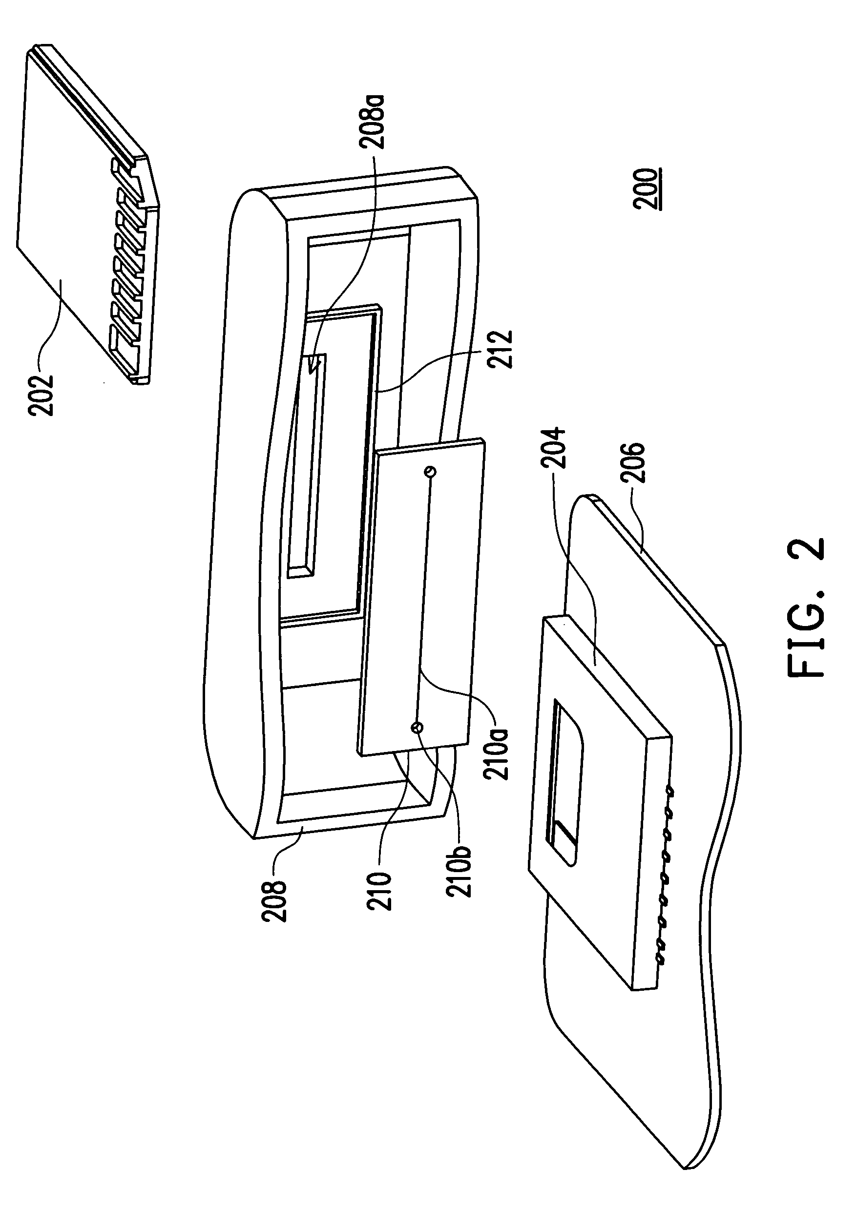
[0009]Accordingly, one object of the present invention is to provide a dust-proof structure for preventing dust from entering a handheld electronic device such as digital camera, PDA or mobile phone, to contaminate a card connector therein. The dust-proof structure has a simple structure and can be easily assembled to the electronic device. Furthermore, the dust-proof structure can effectively block dust from entering the electronic device.

Problems solved by technology

The device usually does not have means on the case for preventing dust from entering into the device through the slot.
When dust enters into the device through the slot, it will accumulate on the connector and contaminate contacts of the connector.
The contamination of the contacts adversely affects a normal connection between the connector and the inserted card, and accordingly, a normal operation of the handheld electronic device.
However, the handheld electronic device lacks a means, which can prevent dust from entering an inside of the device through the slot 108a.
However, due to structural limitation, the dust-proof structure of the prior art cannot be not be easily attached to the card connector of the handheld electronic device to prevent the contamination thereof.
However, the dust-proof structures are mechanisms with a complex setup, numerous parts, a larger size and requires a high production cost.

Method used


Image

  • Dust-proof structure for card connector in handheld electronic device
  • Dust-proof structure for card connector in handheld electronic device
  • Dust-proof structure for card connector in handheld electronic device

Examples


first embodiment

[0019]FIG. 2 is a schematic perspective view of a dust-proof structure 200 according to a first embodiment of the present invention. The dust-proof structure 200 is used for preventing dust or particles from entering an electronic device (not labeled), particularly a handheld electronic device, for example, a personal digital assistant (PDA) or a mobile phone, to contaminate a card connector 204 therein. The electronic device has a case 208 defining a slot 208a through which an electronic card 202 can enter the electronic device to electrically connect with the card connector 204. The card connector 204 is mounted on a printed circuit board 206 in the electronic device. The dust-proof structure 200 includes a frame 212 and a dust-proof gate 210. The frame 212 is configured on the case 208 surrounding the slot 208a of the case 208. The dust-proof gate 210 is secured to an inner surface of the case 208 by an adhesive and located inside the frame 212. The frame 212 fittingly surrounds ...

second embodiment

[0023]FIG. 3 is a schematic perspective view of a dust-proof structure 300 according to a second embodiment of the present invention. The dust-proof structure 300 includes a frame 312 configured on an inner surface of a case 308 and surrounding a slot 308a of the case 308. The dust-proof gate 310 is disposed on an inner surface of the case 308 and surrounded by the frame 312. The dust-proof gate 310 covers the slot 308a to prevent dust or particles from entering into an inside of the case through the slot 308a. The dust-proof gate 310 has a first slit 310a and a second slit 314a, both of which are positioned in communication with the slot 308a. The first slit 310a extends in a longitudinal direction parallel to the longitudinal length of the slot 308a. The second slit 314a is substantially perpendicular to the first slit 310a, extends above the first slit 310a, and connects with a midpoint of the first slit 310a.

[0024]The setup of the second slit 314a can increase the deformation o...

third embodiment

[0025]FIG. 4 is a schematic perspective view showing a dust-proof structure 400 according to a third embodiment of the present invention. The dust-proof structure 400 includes a frame 412 and a dust-proof gate 410. The frame 412 is configured on a case 408 and surrounding a slot 408a in the case 408. The dust-proof gate 410 is disposed on an inner surface of the case 408 and is surrounded by the frame 412. The dust-proof gate 410 covers the slot 408a for preventing dust or particles from entering an inside of the case 408 through the slot 408a. The dust-proof gate 410 has a slit 410a positioned in communication with the slot 408a, wherein the slit 410a is shaped as a wavelike curve. The slit 410a has two ends provided with two respective round holes 410b. The setup of the round holes 410b can avoid the stress concentration during insertion or withdrawal of a card through the slit 410a.

[0026]The dust-proof gate 410 with a non-linear slit 410a can remove dust or particles accumulated...


PUM

PropertyMeasurementUnit
lengthaaaaaaaaaa
longitudinal lengthaaaaaaaaaa
flexibleaaaaaaaaaa

Abstract

A dust-proof structure (200) for an electronic device is disclosed. The electronic device includes a case (208) having a slot (208a) aligned with a card connector (204) in the electronic device. The dust-proof structure includes a frame (212) formed on the case and around the slot, and a dust-proof gate (210) made of resilient material. The dust-proof gate is attached to the case at a position surrounded by the frame and covering the slot. The dust-proof gate has a slit (210a) positioned communicating with the slot, wherein the slit extends along a direction parallel to a longitudinal length of the slot. To insert an electronic card (202) into the electrical device to electrically connect with the card connector, the card is moved first through the slot of the case and then the slit of the dust-proof gate.

Description

CROSS-REFERENCE TO RELATED APPLICATION[0001]This application claims the priority benefit of Taiwan application serial no. 93209624, filed on Jun. 18, 2004.BACKGROUND OF THE INVENTION[0002]1. Field of the Invention[0003]The present invention relates to a dust-proof structure, and more particularly, to a dust-proof structure provided on a case of a handheld electronic device for preventing a card connector in the electronic device from being contaminated by dust.[0004]2. Description of Related Art[0005]The multi-media technology has ushered into a new era. A lot of handheld electronic devices like digital camera, PDA, and mobile phone, have been developed, which are required to embody the multi-media technology and thus need a card connector to connect with a memory card, a game card or an extension card. The card is simply inserted into a case of the device through a slot in the case to connect with the card connector. The device usually does not have means on the case for preventing...

Claims


Application Information

Patent Timeline
Patent Type & Authority Patents(United States)
IPC IPC(8): H01R13/44G06K13/08G11B33/14H01R13/52H05K5/02H05K5/06
CPCG06K13/08G06K13/0893H05K5/0239H01R13/5202G11B33/1446H05K5/03
Inventor SHIUE, JIH-JENGYEH, JIH-CHEN
Owner HTC CORP
Learn More