
Seal device

Inactive Publication Date: 2006-08-22
EAGLE INDS
View PDF4 Cites 6 Cited by
  • Summary
  • Abstract
  • Description
  • Claims
  • Application Information

AI Technical Summary

Benefits of technology

[0026]In a seal device related to the present invention, since a first seal portion of a first resilient body element and a first seal portion of a second resilient body element are supported by individual first support portions the respective first seal portions effectively maintain stable sealing relations with individual mounting surfaces. Also the individual support portions are capable of providing a secure support to the first resilient seal portion and the second resilient seal portion even when the individual first seal portions are subject to external forces. Therefore the individual first seal portions hardly allow slurry or impurities to go into the interface between the first seal portion and its mating fixing portion, and a decline of the seal capability at the interfaces due to wear of the first seal portions is effectively prevented. A second seal portion of the first resilient body element as well as a second seal portion of the second resilient body element provide a similar effect to the first seal portions do. In particular, the individual second seal portions provide a secure support against the seal rings. And a first elastic portion and second elastic portion give a resilient reinforcement to the first resilient seal portion and the second resilient seal portion, respectively, such that a decrease in the elastic force due to a stress relaxation of the first resilient seal portion and the second resilient seal portion is supplemented.

Problems solved by technology

Therefore a choice of hardness in rubber materials may vary and it makes difficult to make an optimal decision of rubber materials.

Method used


Image

  • Seal device
  • Seal device
  • Seal device

Examples


first embodiment

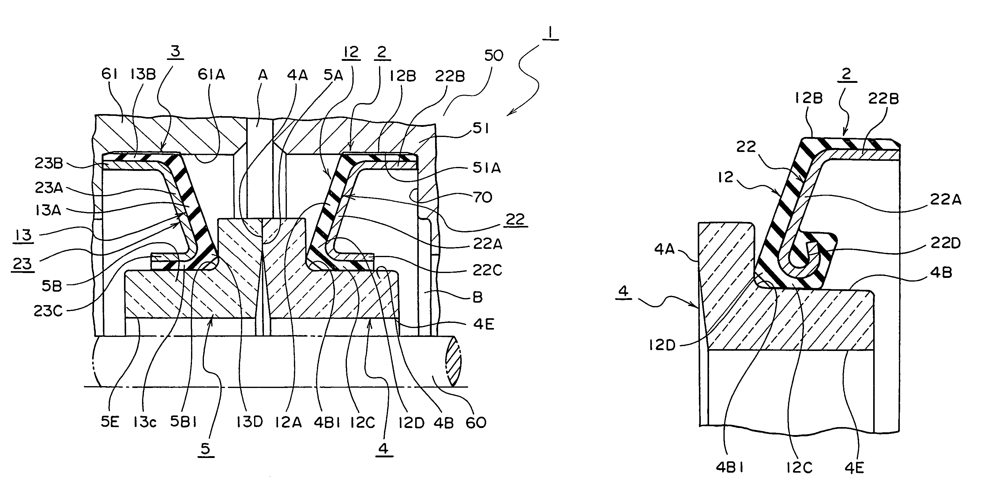
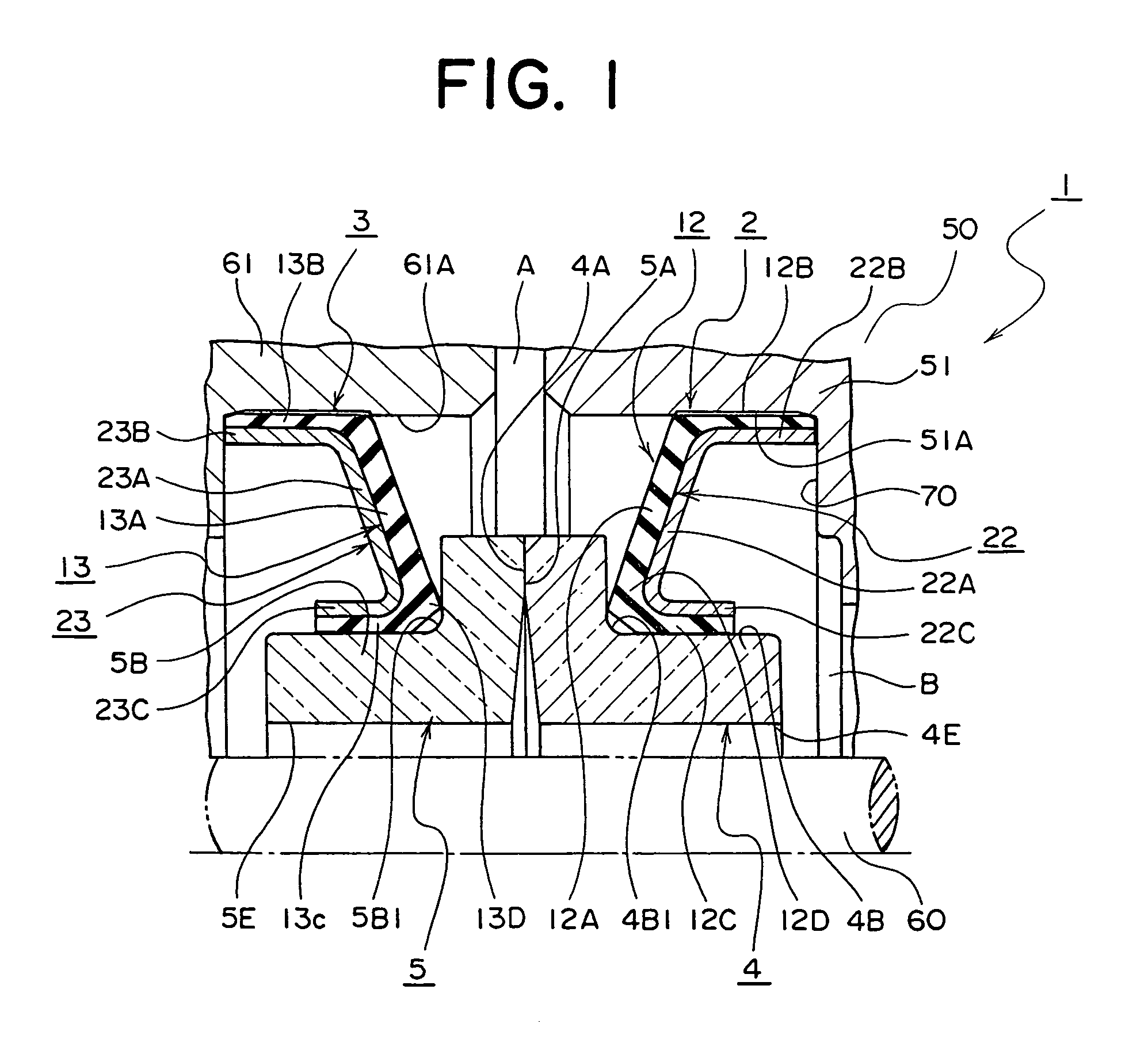
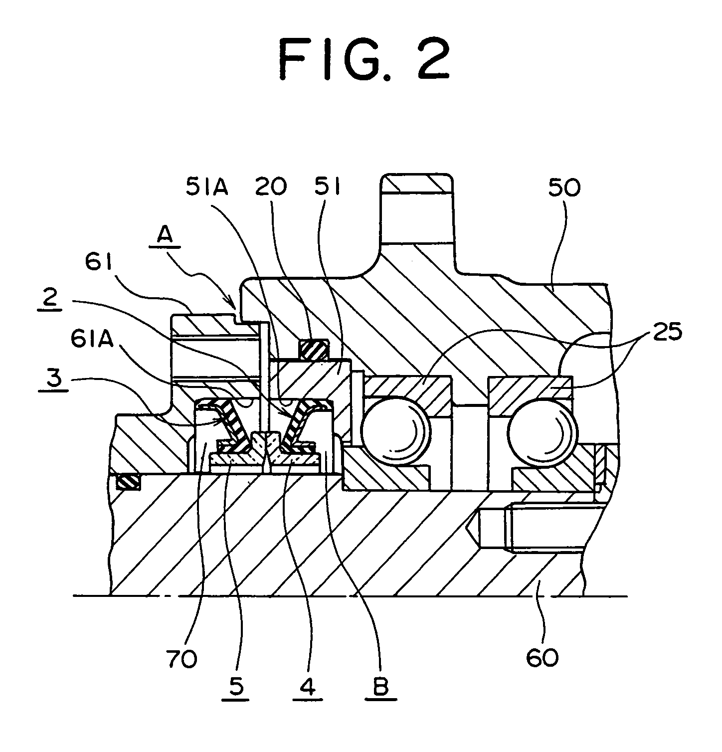
[0037]Described below is details of the figures of preferred embodiments of the present invention according to actual design drawings with accurate dimensional relations. FIG. 1 is a cross-sectional view of a half portion of a seal device 1 illustrating a first embodiment related to the present invention. FIG. 2 is a cross-sectional view of a half portion of a reduction gear unit mounting the seal device 1 of FIG. 1.

[0038]In FIG. 1 and FIG. 2, the seal device 1 is disposed within a seal chamber 70 which is formed between a roller 50 and a shaft 60. The seal chamber 70 is defined as an inner space surrounded by the shaft 60, a first fixture surface 51A of a bushing 51 which is mounted via a O-ring 20 at the end portion of the roller 50, and a second fixture surface 61A of a cover 61 which is attached to the shaft 60. This seal chamber 70 communicates with an ambient communication passage A.

[0039]The seal device 1 retains a first resilient seal ring 2 and a second resilient seal ring ...

second embodiment

[0066]Since the seal device 1 related to the second embodiment disposes the first reinforcement ring 22 and / or the second reinforcement ring 23 with notch portions 26 or slit portions 26 therein, the individual elastic portions 22A, 23A between the adjacent notches 26 or slits 26 can be considered as leaf springs, so that the resilient forces exerted by the elastic portions 22A, 23A can be arbitrarily designed (or spring forces of the elastic portions 22A, 23A can be adjusted according to design specifications). At the same time, introducing a portion of the material of the resilient seal portions 12A, 13A into the notch portions 26 or the slit portions 26 in the manufacturing process of the resilient seal portions 12A, 13A, provides an improvement on the integral force between the individual resilient seal portions 12A, 13A and corresponding reinforcement rings 22, 23, respectively. The notch portion 26 or slit portion 26 may be fabricated like a rectangular window in the elastic p...

third embodiment

[0068]A seal device 1 as a third embodiment related to the present invention disposes a first reinforcement ring 22 of a first resilient seal ring 2 at the opposite side of the first resilient seal ring 2 with respect to a process fluid and a second reinforcement ring 23 of a second resilient seal ring 3 at the opposite side of the second resilient seal ring 3 with respect to the fluid.

[0069]In the seal device 1 as a third embodiment related to the present invention, since the first reinforcement ring 22 and the second reinforcement ring 23 are mounted onto the first resilient seal ring 2 and the second resilient seal ring 3, respectively, at the opposite side relative to the process fluid, it is less likely for inclusions in the fluid to go into between the mating surfaces at the individual contact surfaces, i.e., first seal portions 12B, 13B and second seal portions 12C, 13C, and this prevents the inclusions from causing abrasion of the mating contact surfaces and the individual s...


PUM


Abstract

A seal device includes a first resilient seal ring having a first resilient seal portion and first and second seal portions; and a second resilient seal ring. The first resilient seal portion urges a first seal surface of the first seal ring against the second seal surface of the second seal ring. The second seal portion mates with the first retainer portion of the first seal ring, while the first seal portion is in a sealing relation with one component. The second resilient seal ring has a second resilient seal portion, and first and second seal portions. The second resilient seal portion urges a second seal surface of the second seal ring against the first seal surface of the first seal ring, while the second seal portion mates with the second retainer portion of the second seat ring.

Description

BACKGROUND OF THE INVENTION[0001]1. Field of the Invention[0002]The present invention relates to a seal device disposed between a pair of relatively rotating elements typically seen in the rollers of a crawler, track roller, reduction gear, hydraulic motor or the like. More particularly, the invention relates to a seal device in the reduction gear unit of automobiles or hydraulic motors of a variety of machinery, which provides an effective seal at the interface of relatively moving elements against a process fluid containing slurry or a high pressure process fluid.[0003]2. Description of the Related Art[0004]Primary related art of the present invention is found as a seal ring in U.S. Pat. No. 6,086,069. A similar type of seal ring as the one shown in U.S. Pat. No. 6,086,069 is illustrated, for example, in FIG. 8. The seal ring 101 in FIG. 8 is, for example, mounted to a crawler unit 100.[0005]In FIG. 8, 120 represents a shaft. The shaft 120 is disposed within a through bore of a ro...

Claims


Application Information

Patent Timeline
IPC IPC(8): F16J15/34F16J15/00F16J15/38F16J15/36
CPCF16J15/36F16J15/344
Inventor TSUBOI, HAJIMEMARUYAMA, HIDEKI
Owner EAGLE INDS
Learn More