Fence and method of producing such

Inactive Publication Date: 2006-08-15
XFM
View PDF17 Cites 27 Cited by
  • Summary
  • Abstract
  • Description
  • Claims
  • Application Information

AI Technical Summary

Benefits of technology

[0009]The present invention meets the need in the art by providing a fence panel that readily adjusts to conform substantially to a slope of a terrain during installation of the fence panel. The fence panel tracks a sloped grade of a portion of a terrain surface for attaching to adjacent ones of the fence panel to define an elongate length of fencing along the terrain surface, comprises a first rail disposed parallel and spaced-apart from a second rail, which rails define a longitudinal length of a fence panel. Each rail defines on a side opposing spaced-apart first and second side edges, with the rails disposed at an angle relative to horizontal. A plurality of spaced-apart pickets define a pair of second pickets and a plurality of first pickets. The pickets ar

Problems solved by technology

This method of producing fencing is time consuming and inefficient.
However, during the manufacturing, the terrain may have changed.
For example, a pool area to be fenced may change due to subterranean problems such as rocks and the like uncovered during installation of the pool.
This results in re-work or scrap sections of fencing, which increases the costs of the fencing.
While this shifting of the fence panel has worked fairly well when shifting only a small amount or a few degrees, there is a problem with more significant changes in the angle of the rails relative to the pickets.
The rails and pickets there are not square to each other and the fence has unsatisfactory gaps at the connections between the rails and the pickets.
The gaps weaken the fence panel and are unsightly.

Method used


Image

  • Fence and method of producing such
  • Fence and method of producing such
  • Fence and method of producing such

Examples


Embodiment Construction

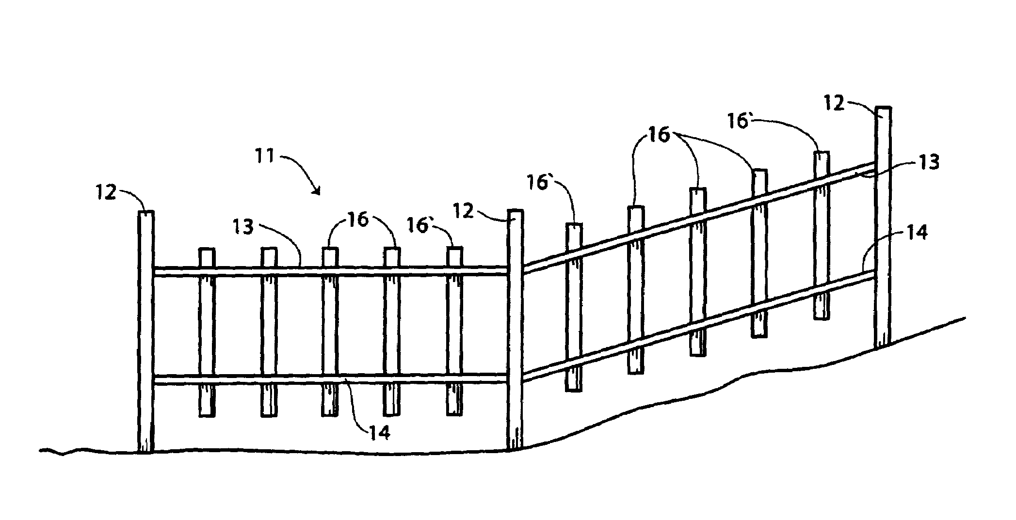
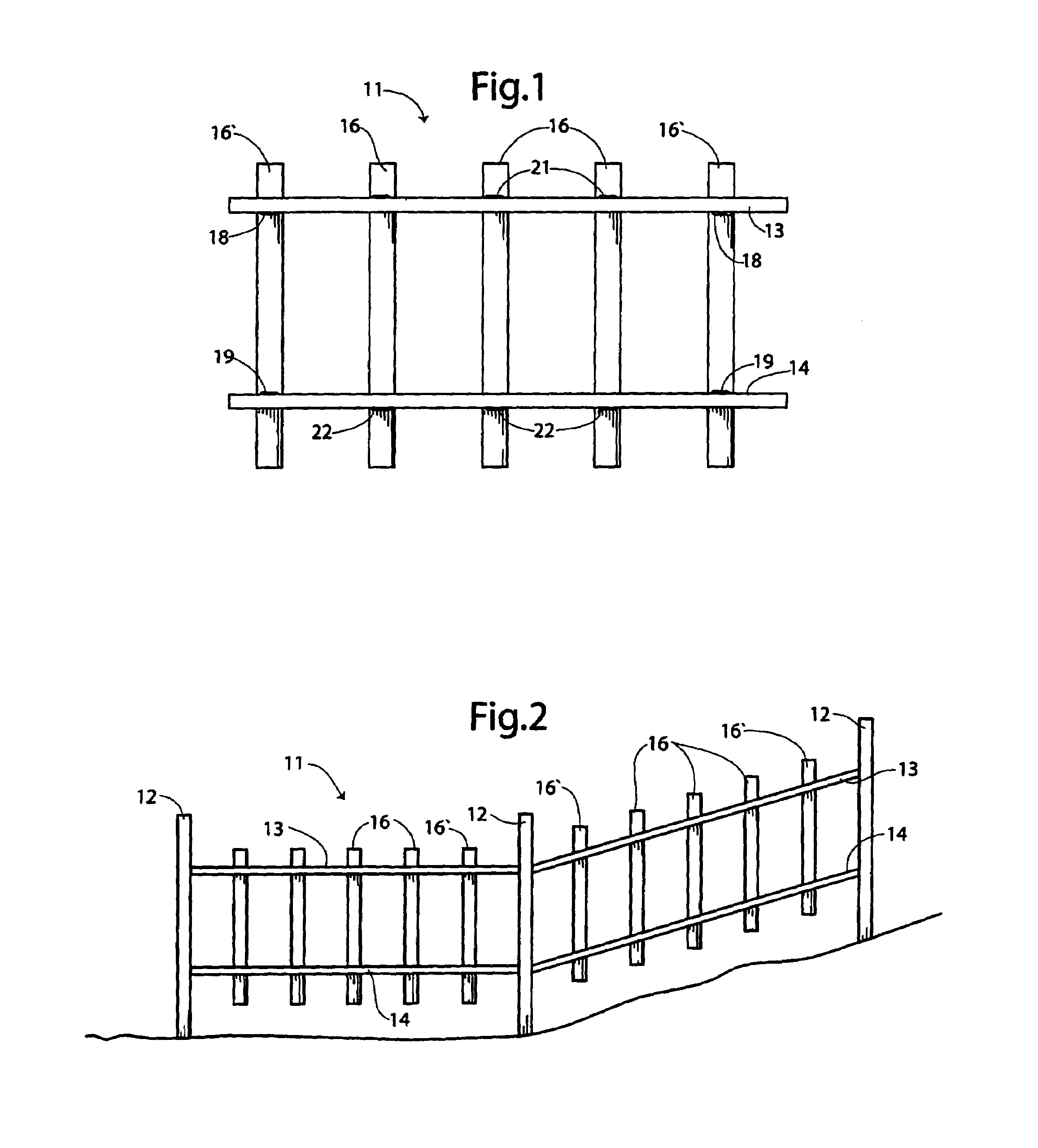
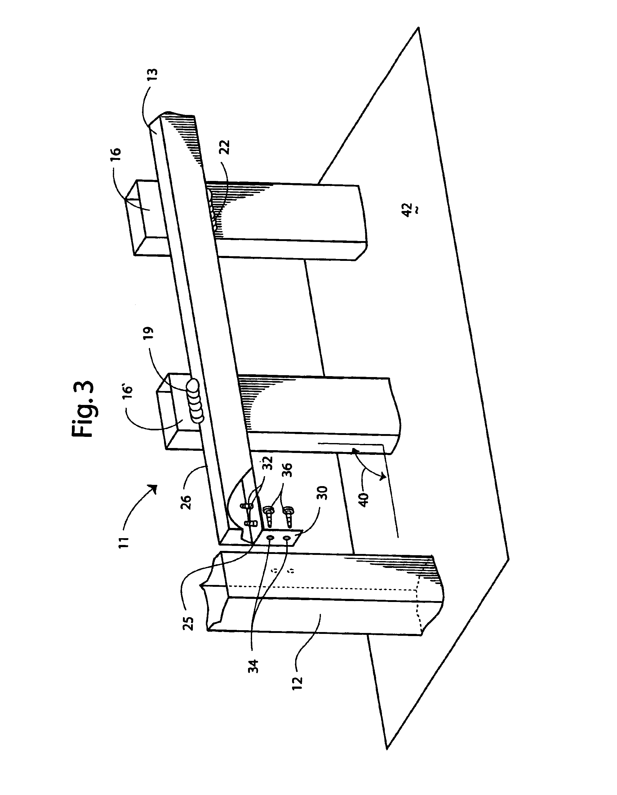
[0022]Referring now in more detail to the drawings, in which like numerals indicate like parts throughout the several views, FIG. 1 illustrates a fence 10 embodying principles of the invention in a preferred form. The fence 10 has a series of panels or sections 11 mounted to a series of posts 12. Each section 11 includes a top rail 13, a bottom rail 14, and a series of pickets 16 mounted to the top rail 13 and the bottom rail 14. Each rail 13, 14 defines a lower side edge 25 and an upper side edge 26 which side edges abut against a face of the pickets 16 (see FIG. 3), for a purpose discussed below. In the illustrated embodiment, the rails and the pickets are metal.

[0023]The outermost pickets 16′ and 16′ of each section 11 mount or fasten to the top rail 13 with a lower, flexible, mild steel weld 18 extending along the lower edge 25 of the top rail 13, and mount to the bottom rail 14 with an upper, flexible, mild steel weld 19 extending along the upper edge 26 of the bottom rail 14. ...


PUM


Abstract

A fence panel that tracks a sloped terrain surface, in which a pair of spaced-apart rails each have a first longitudinal edge and an opposing second longitudinal edge on a side of the rail, and a plurality of pickets having first pickets and at least two second pickets disposed spaced apart on the side of the rails, with the first pickets attached by a fastener only between the picket and the first longitudinal edge of the respective rail and the second pickets attached by a fastener only between the picket and the second longitudinal edge of the respective rail, so that the rails do not roll away from the pickets when racking the fence panel by moving the opposing ends of the rails in vertically opposite directions to conform the slope of the fence panel to the terrain surface. A method of making a fence panel is disclosed.

Description

[0001]The present application is a continuation-in-part of co-pending provisional application Ser. No. 60 / 258,220, filed Dec. 26, 2000.TECHNICAL FIELD[0002]This invention relates to fencing and methods of producing fencing, and more particularly, the present invention relates to rail and picket fencing that is selectively angled on site to conform the slope of the fencing to the slope of an underlying terrain.BACKGROUND OF THE INVENTION[0003]Fencing has existed for many years. In particular, wrought iron fencing or the like has been developed to produce a more decorative type of fencing. This type of fencing comprises a series of vertical pickets which are attached to horizontal rails. In some known types of wrought iron fencing, the rails have holes through which the pickets extend. Screws connect the pickets attach to the rails with screws or by welding.[0004]In the past, wrought iron fencing erected upon a sloping terrain was typically produced on site by planting several spaced-...

Claims


Application Information

Patent Timeline
IPC IPC(8): E04H17/14
CPCE04H17/1434E04H2017/1491E04H17/143E04H17/1448
Inventor O'BRIEN, JAMES RICHARD
Owner XFM
Why Eureka
Try Eureka