
Gauge carrier sub apparatus

a sub-assembly and gauge technology, applied in the field of gauges, can solve problems such as being damaged or destroyed

Inactive Publication Date: 2006-08-15
WARRIOR ENERGY SERVICES
View PDF10 Cites 6 Cited by
  • Summary
  • Abstract
  • Description
  • Claims
  • Application Information

AI Technical Summary

Benefits of technology

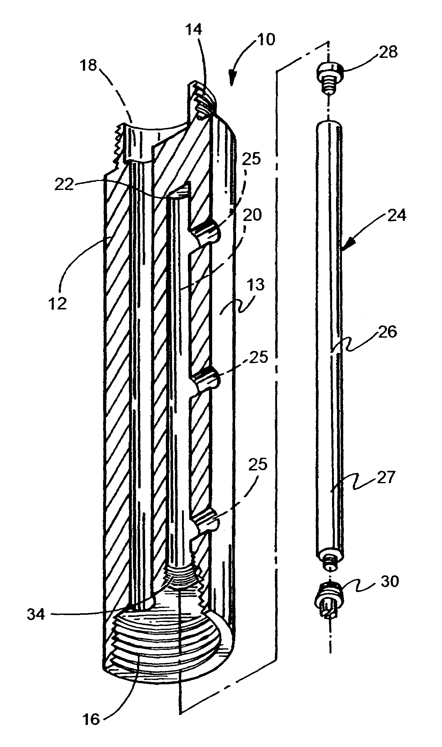
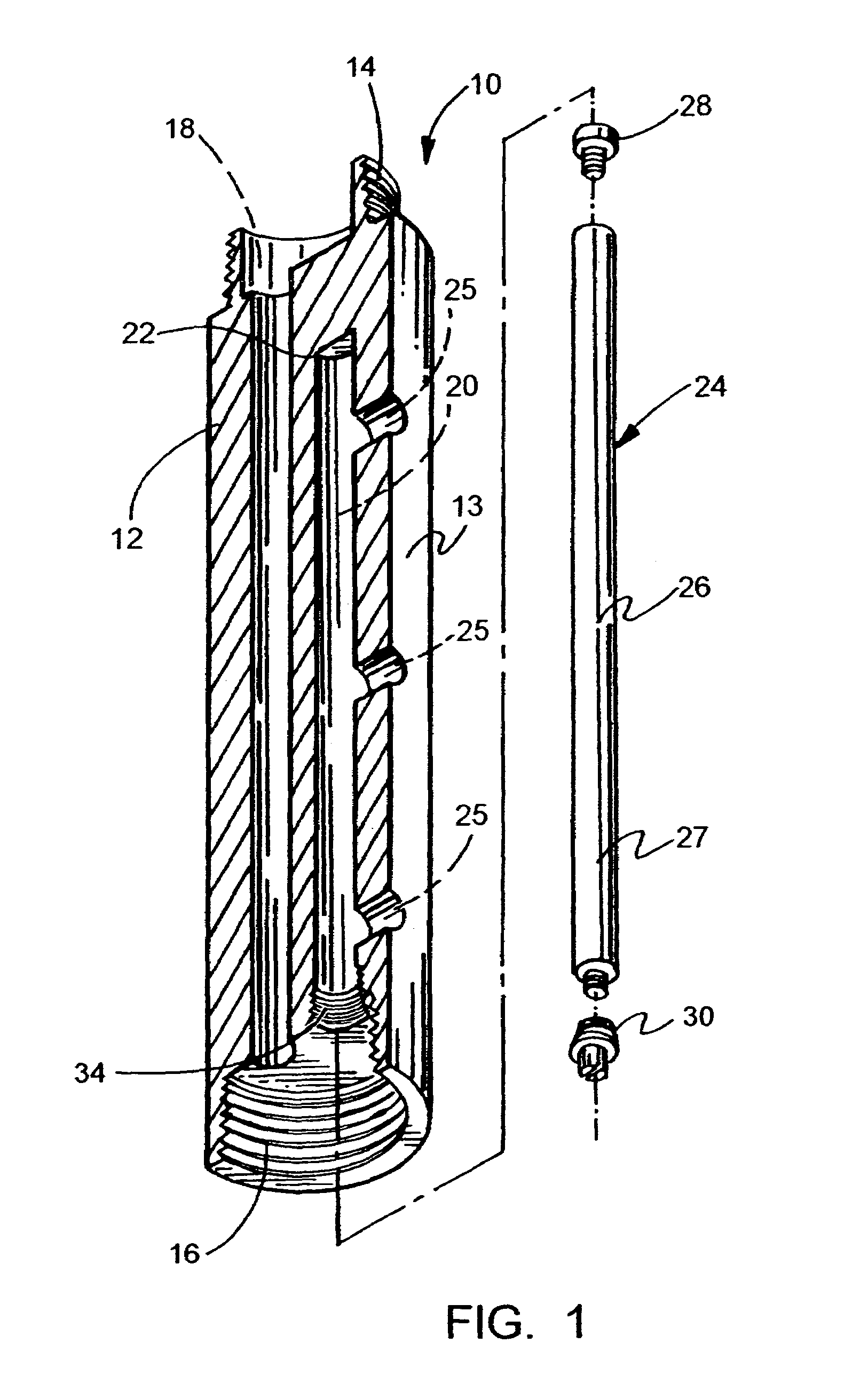
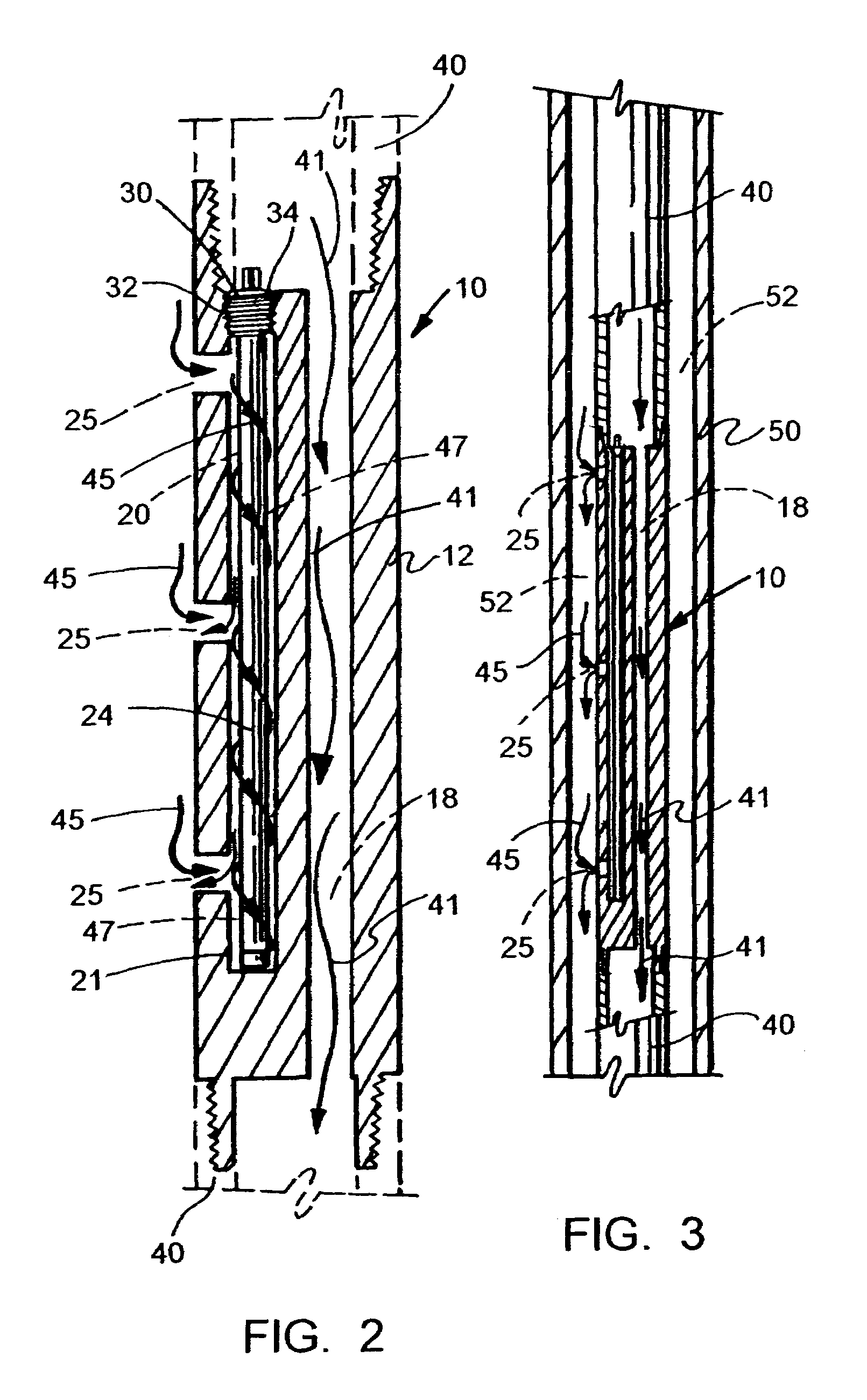
[0010]The present invention solved the problems in the art in a simple and straight forward manner. What is provided is a sub apparatus for carrying a gauge down a well bore, which includes a sub body having a first and second ends threadably engageable to sections of pipe in the drill or production string; the sub body including a first chamber for housing the gauge; a second bore through the sub body for allowing fluid to flow through the sub within the pipe; a plurality of openings in the wall of the sub at points to allow fluids within the pipe to make fluid contact with the gauge; means for protecting the gauge on a first end and for engaging the gauge to the sub on a second end.
[0012]It is a further object of the present invention to provide a sub for a gauge lowered down a well bore for protecting the gauge from harmful contact and yet allowing the gauge to obtain accurate readings down the well bore;
[0013]It is a further object of the present invention to provide a sub apparatus having a protective chamber for a gauge within the sub, and allowing fluid in drill or production string to flow through the gauge unimpeded.

Problems solved by technology

One of the problems in such monitoring with gauges are that the gauges, which by their nature, are very sensitive, are subject to harsh conditions down the well bore, and are subject to being damaged or destroyed by foreign objects down the well bore.

Method used


Image

  • Gauge carrier sub apparatus
  • Gauge carrier sub apparatus
  • Gauge carrier sub apparatus

Examples


Embodiment Construction

[0018]FIGS. 1 through 3 illustrate the preferred embodiment of the present invention by the numeral 10. As illustrated, the gauge protection sub 10 comprises a generally cylindrical body 12, having a continuous circular sidewall 15, which terminates in a first pin end 14 and a box end 16, the ends 14, 16, threaded in order to be threadably engaged to a length of drill pipe, production pipe or other threaded members in a drill or production string. The body 12 in constructed of a durable material, such as tempered steel or the like so as to withstand contact with foreign objects down a well bore, as the sub 10 is moved down a well bore as part of the drill or production string. The sub body 12 also includes a first bore 18 extending from the pin end 14 through the box end 16, through the entire body 12, so as to allow fluid flow through the bore 18, for the reasons as will be explained further.

[0019]The sub body 12 also includes a chamber 20 which would extend from the box end 16 of ...


PUM


Abstract

A sub apparatus for delivering and protecting a gauge being lowered down a well bore, which includes a sub body having a first and second ends threadably engageable to sections of pipe in the drill or production string; the sub body including a first chamber for housing the gauge; a second bore through the sub body for allowing fluid flowing within the drill or production string to flow through the sub; a plurality of openings formed in the wall of the sub in fluid communication with the first chamber to allow fluids within the pipe to make fluid contact with the gauge; means for protecting the gauge on a first end and means for engaging the gauge to the sub on a second end.

Description

CROSS-REFERENCE TO RELATED APPLICATIONS[0001]Not applicableSTATEMENT REGARDING FEDERALLY SPONSORED RESEARCH OR DEVELOPMENT[0002]Not applicableREFERENCE TO A “MICROFICHE APPENDIX”[0003]Not applicableBACKGROUND OF THE INVENTION[0004]1. Technical Field of the Invention[0005]The apparatus of the present invention relates to gauges used down a bore hole. More particularly, the present invention relates to a sub which is designed to carry sensitive gauges, which measure conditions down the bore hole, in order to protect the gauge from damage.[0006]2. General Background of the Invention[0007]In the very complex operation of drilling and completing oil and gas wells, it is critical that the conditions down the bore hole, such as temperature and pressure of the fluid, or of the surrounding earth are constantly monitored in order to avoid problems, such as blowout or other adverse conditions to arise. This monitoring is often down by gauges or other types of instruments which are lowered down...

Claims


Application Information

Patent Timeline
Patent Type & Authority Patents(United States)
IPC IPC(8): E21B47/01
CPCE21B47/011E21B47/017
Inventor MARTIN, TODD
Owner WARRIOR ENERGY SERVICES
Learn More