Lens collimator and method of producing optical signals with reduced aberrations

a collimator and lens technology, applied in the field of lenses, can solve the problems of degrading the produced optical signal, affecting the quality of optical signals, and affecting the quality of optical signals, and achieve the effect of light weigh

Inactive Publication Date: 2006-08-08
HARRIS CORP
View PDF21 Cites 6 Cited by
  • Summary
  • Abstract
  • Description
  • Claims
  • Application Information

AI Technical Summary

Benefits of technology

[0010]Accordingly, it is an object of the present invention to construct a lens that is small (e.g., compact, low volume, etc.), light weight and sturdy and that may be utilized for several purposes simultaneously.
[0011]It is another object of the present invention to construct a lens of a plurality of elements arranged to produce an enhanced quantity of reflections and refractions within a lens optical path in order to reduce aberrations.
[0012]Yet another object of the present invention is to form a lens of a bonded assembly with a carrier medium attached to the lens at a focal plane adjacent one of the lens elements, thereby enabling the lens to maintain alignment and either be in an operational state or a disabled state (e.g., in other words, preventing the lens from operating in an impaired state).
[0014]A further object of the present invention is to construct a lens that enables optical signals to be widely spaced in order to provide increased area for additional optical components.
[0016]According to the present invention, a lens collimator includes a plurality of lens elements bonded together. The lens elements, preferably three, each include spherical surfaces and are generally concentrically disposed relative to each other. The lens elements are arranged to produce an increased quantity of reflections and refractions within a lens optical path. The reflections and refractions reduce aberrations and control signal intercept angles relative to an image plane, thereby enabling the lens to match the performance of an optical signal carrier utilized with the lens. The lens element arrangement basically serves to provide an optical path with a quantity of reflections and refractions similar to that achieved with a lens having a greater quantity of elements or surfaces. The reflections and refractions enable the lens to cancel out or remove undesired characteristics (e.g., aberrations, etc.) from the resulting optical signals.
[0017]The present invention provides several advantages. In particular, the reflections provide a folded or tortuous optical path, thereby enabling the lens to be small (e.g., small volume and size) and lightweight. The lens includes a bonded assembly with a focal plane at or near a lens element surface. A carrier (e.g., fiber, etc.) utilized with the lens is typically attached to the lens at the focal plane, where the combination provides a rugged assembly that maintains alignment and is substantially insensitive to vibration and shock. Thus, the lens enters either an operational state or a disabled state and thereby does not function in an impaired or broken state. Further, the lens is substantially temperature insensitive, especially when the propagation length in air is minimal and / or the image is at the lens surface. This is due to the lens being in the form of a single unit with elements constructed of similar materials. Basically, the lens expands from heat and moves the focal plane relative to the lens. However, the carrier attached to the lens within the focal plane similarly expands, thereby maintaining the lens in focus. Moreover, the f-number (e.g., focal length / diameter) of the lens enables optical signals to be spaced widely upon entry and exit, thereby providing extra space for additional optics.

Problems solved by technology

However, these types of lenses produce aberrations that degrade the produced optical signals.
However, some may employ a folded optical path, where the quantity of folds is limited.
Although the above types of lenses are generally easier to fabricate and less expensive, the dimensions and weight of these lenses are usually significant.
Further, the reduced quantity of folds or reflections and refractions in a lens optical path has a deleterious effect on aberrations, thereby producing a degraded beam or requiring additional components to compensate for the adverse effects.
Enhancing the quality of reflections in a single element lens significantly increases fabrication and associated costs.
Post-turning polishing in these circumstances is extremely difficult and tends to adversely affect the surface accuracy.

Method used


Image

  • Lens collimator and method of producing optical signals with reduced aberrations
  • Lens collimator and method of producing optical signals with reduced aberrations
  • Lens collimator and method of producing optical signals with reduced aberrations

Examples


Embodiment Construction

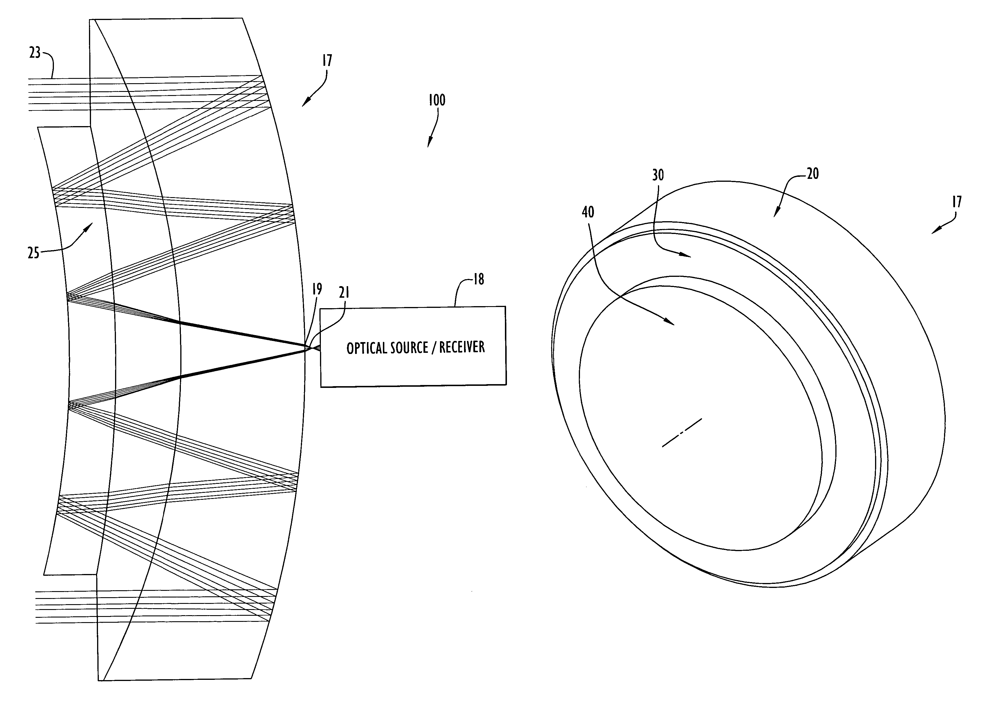
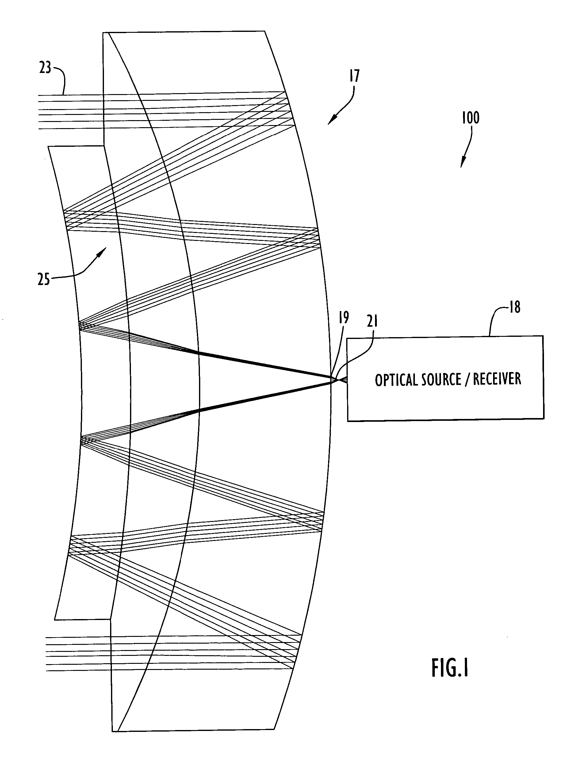
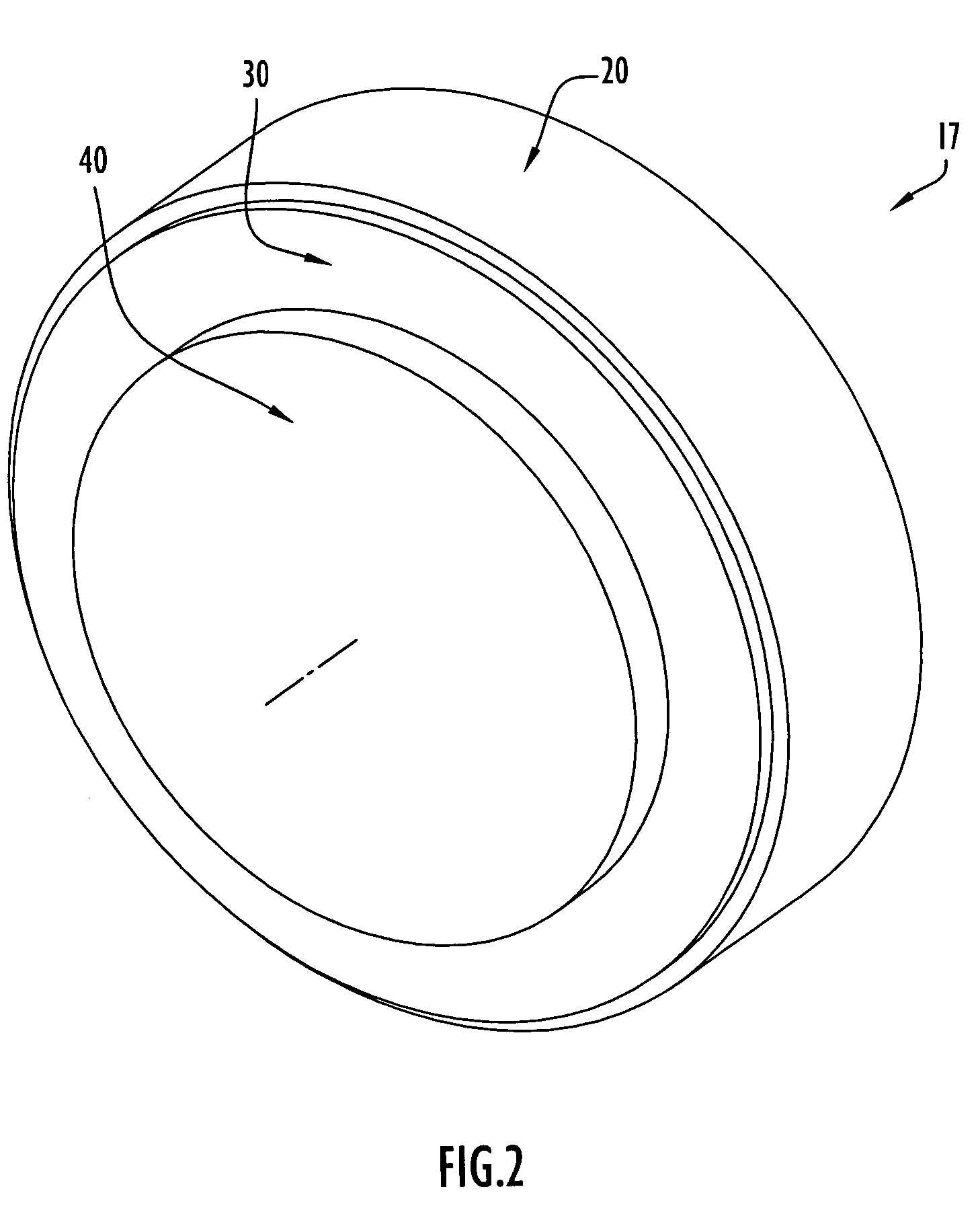
[0028]An exemplary optical communications unit employing a lens collimator of the present invention is illustrated in FIG. 1. Initially, optical communications unit 100 may be utilized in an optical communications system to optically transfer (e.g., transmit and / or receive) information between communication system sites. Specifically, unit 100 includes a lens collimator 17, an optical signal device 18 and an optical signal carrier 21. Lens 17 is typically mounted in a holder (not shown), while this type of application may further include additional optics (not shown). Unit 100 may be in the form of an optical transmitting or receiving unit, where device 18 may be a laser transmitter or an optical receiver to process incoming optical signals, respectively. Alternatively, the unit may be in the form of a transceiver, where device 18 transmits and receives optical signals.

[0029]Device 18 is coupled to lens 17 via optical signal carrier 21, preferably in the form of communications grade...


PUM


Abstract

A lens collimator according to the present invention includes a plurality of lens elements bonded together. The lens elements, preferably three, each include spherical surfaces and are generally concentrically disposed relative to each other. The lens elements are arranged to produce an increased quantity of reflections and refractions within a lens optical path. The reflections and refractions reduce aberrations and control signal intercept angles relative to an image plane, thereby enabling the lens to match the performance of an optical signal carrier utilized with the lens. The lens element arrangement basically serves to provide an optical path with a quantity of reflections similar to that achieved with a lens having a greater quantity of elements or surfaces. The reflections and refractions enable the lens to cancel out or remove undesired characteristics (e.g., aberrations, etc.) from the resulting optical signals.

Description

STATEMENT REGARDING FEDERALLY SPONSORED RESEARCH OR DEVELOPMENT[0001]The invention was made with Government support and the Government may have certain rights in the invention.BACKGROUND OF THE INVENTION[0002]1. Technical Field[0003]The present invention pertains to lenses. In particular, the present invention pertains to a lens collimator, preferably for optical communication systems, that provides optical signals with reduced aberrations. The lens collimator includes a plurality of lens elements that provide an increased quantity of surfaces for optical signal reflections and refractions to occur within the lens optical path, thereby enabling the lens collimator to cancel out adverse effects (e.g., aberrations, etc.) from the resulting optical signals or beam.[0004]2. Discussion of Related Art[0005]Optical communication systems employ optical or light signals to transfer information between system sites. Interconnection between local system sites may employ media, such as fiber op...

Claims


Application Information

Patent Timeline
Patent Type & Authority Patents(United States)
IPC IPC(8): G02B17/00G02B17/08
CPCG02B17/004G02B17/086G02B17/0808G02B17/0804
Inventor BRAUN, LEROY O.
Owner HARRIS CORP
Why Eureka
Try Eureka