Wellbore anchor tool

a technology for anchoring tools and wellbores, applied in the direction of tubing catchers, borehole/well accessories, fluid removal, etc., can solve the problems of uneven cut, small distance critical, and more pronounced problem

Inactive Publication Date: 2006-08-08
ABRADO INC
View PDF3 Cites 4 Cited by
  • Summary
  • Abstract
  • Description
  • Claims
  • Application Information

AI Technical Summary

Benefits of technology

[0005]It is, therefore, an object of the present invention to provide a well bore anchor tool, which is adapted for engaging the inner wall of the casing, and stabilize any attached equipment within the well bore.

Problems solved by technology

However, this small distance is critical in the tight confines of a casing.
The deeper the casing cutting operations are performed, the more pronounced the problem becomes.
Even then, a possibility exists for the hydraulic force imparted on the cutter to unseat the plate, which will result in an uneven cut.

Method used


Image

  • Wellbore anchor tool
  • Wellbore anchor tool
  • Wellbore anchor tool

Examples


Embodiment Construction

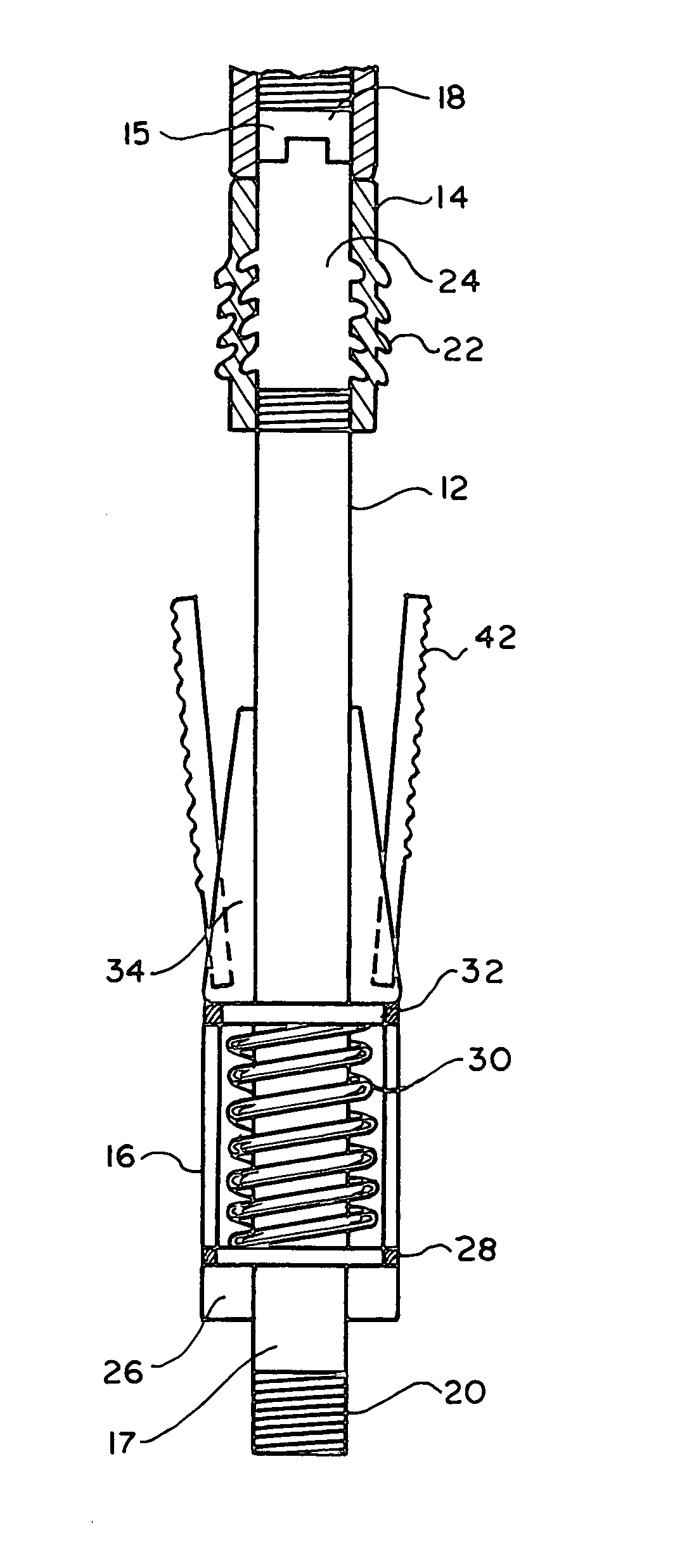
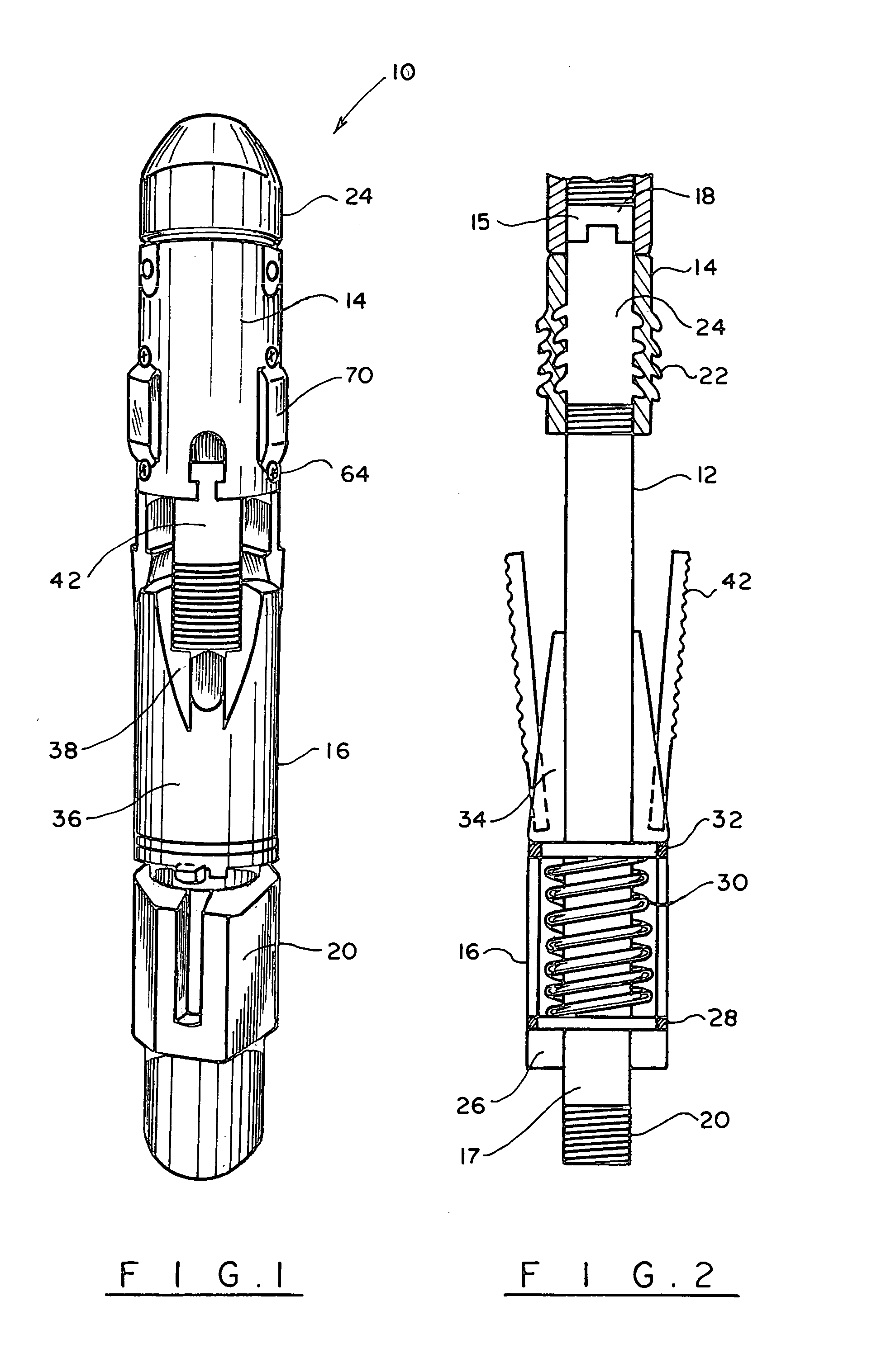
[0030]Turning now to the drawings in more detail, numeral 10 designates the well bore anchor tool in accordance with the present invention. The anchor tool 10 comprises an elongated central mandrel 12 having an upper sub 14 and a bottom sub 16 secured thereto. A top sub 15 has exterior threads 18 which allow securing of a work string thereto. A lower sub 17 is similarly provided with exterior threads 20 that allow securing of a downhole tool, for instance a sand cutter thereto.

[0031]A wicker sleeve 24 is mounted in a threadable engagement with the upper part of the mandrel 12. The wicker sleeve has exterior threads 22 formed along at least a lower portion the wicker sleeve 24. The upper part of the wicker sleeve 24 has a smooth exterior surface. A plurality of wicker dogs 94 is threadably engaged with the threads 22, as will be explained in more detail hereinafter.

[0032]An annular collar 26 is secured about a lower portion of the mandrel 12. A split thrust 28 rests with its bottom s...


PUM


Abstract

An anchor assembly for a downhole tool has upper and lower frictional engagement member for engaging with an inner wall of the casing. The upper frictional members are spring-tensioned, while the lower frictional engagement members slide, to certain degrees, in relation to a longitudinal axis of the anchor assembly. At the same time conical engagement between the lower frictional members and the supporting surface causes the lower frictional members to extend outwardly and engage the inner surface of the casing. As a result, the working tool, for instance a sand cutter secured to the anchor assembly is stabilized in the casing, and an even cut may be performed.

Description

BACKGROUND OF THE INVENTION[0001]This invention relates to downhole anchoring tools, and more particularly to a well bore anchor that may be used for stabilizing a sand cutter and similar equipment in the well bore during a cutting operation.[0002]In well operations, sometimes a well must be abandoned and plugged. The government regulations require that a casing be cut at a certain depth below the surface. Sand cutters have been conventionally used for performing the cutting operation. It was noted that when the cutting is performed at the depth of about 100 feet, the pressures downhole tend to push and excite the nozzle of the sand cutter and move it out of alignment by a small distance, such as a quarter of an inch. However, this small distance is critical in the tight confines of a casing. The string supporting the cutter is energized and causes it to move from the required alignment. As a result, the cut created by the sand cutter is no longer circular but rather resembles a spi...

Claims


Application Information

Patent Timeline
Patent Type & Authority Patents(United States)
IPC IPC(8): E21B23/01E21B23/04E21B29/00E21B43/04
CPCE21B29/002E21B23/01
Inventor RUTTLEY, DAVID J.BOUDET, HENRY P.
Owner ABRADO INC
Why Eureka
Try Eureka