Valve arrangement for a small hermetic compressor

Inactive Publication Date: 2006-08-01
EMBRACO IND DE COMPRESSORES E SOLUCOES EM REFRIGERACAO LTDA
View PDF15 Cites 17 Cited by
  • Summary
  • Abstract
  • Description
  • Claims
  • Application Information

AI Technical Summary

Benefits of technology

[0011]Thus, it is an object of the present invention to provide a suction and discharge valve arrangement for a small hermetic compressor, which allows positioning the discharge orifice in the valve plate in a way that minimizes the pressure differentials existing in the known prior art constructions, reducing the power dissipation and load loss during compression, without impairing the gas flow effective area through the suction orifice, as well as the minimum spacing of the latter in relation to the discharge orifice.

Problems solved by technology

This additional power may be called over-pressure power and decreases the energetic efficiency of the compressor.
In this situation, the piston is very close to the upper dead point of the mechanism, resulting in a compression chamber with small height, which greatly increases the load loss of the gas that has to flow to the discharge orifice and then flow through the discharge valve.
The more eccentric the position of the discharge orifice, the greater will be the loss.

Method used


Image

  • Valve arrangement for a small hermetic compressor
  • Valve arrangement for a small hermetic compressor
  • Valve arrangement for a small hermetic compressor

Examples


Embodiment Construction

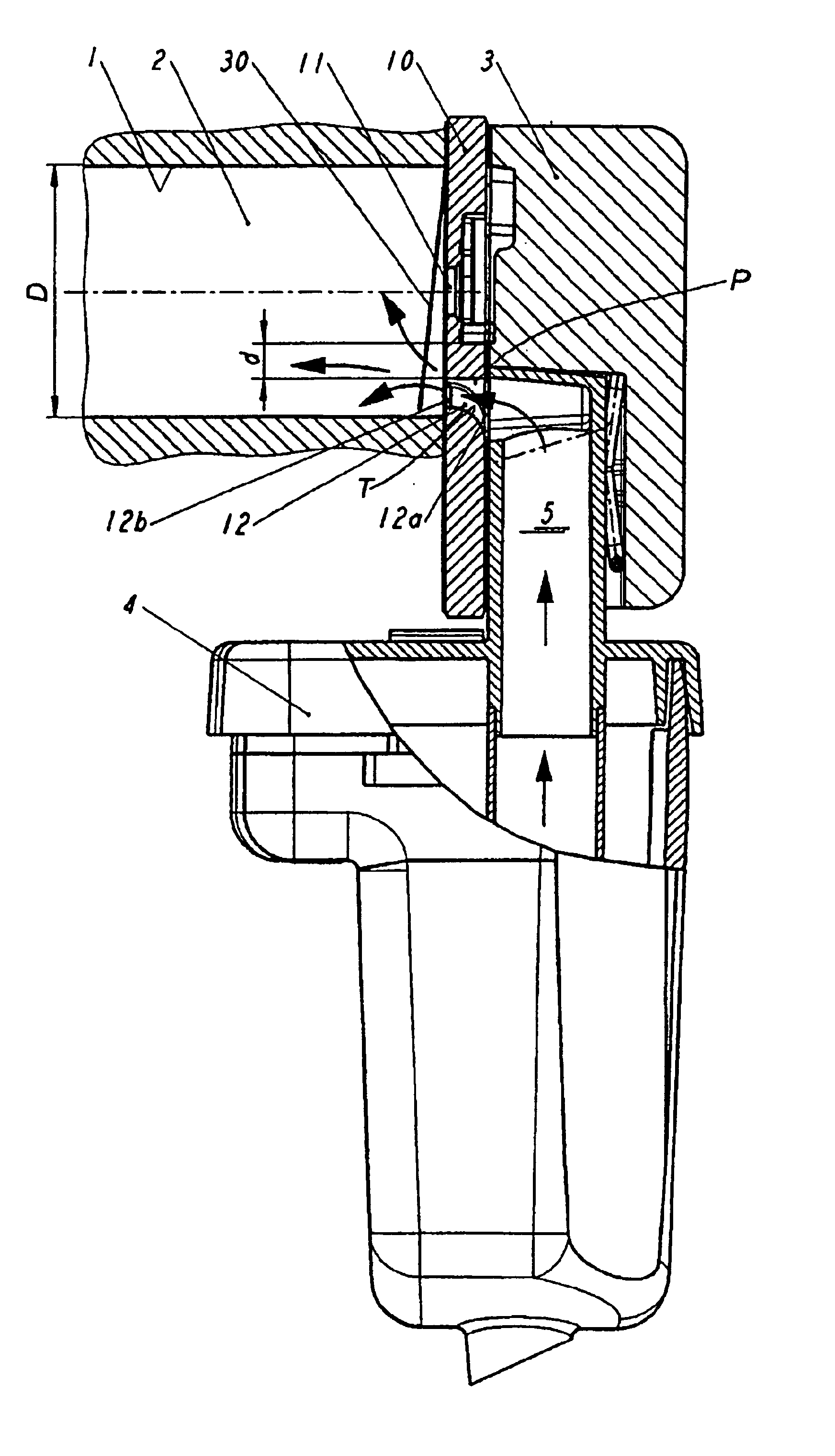
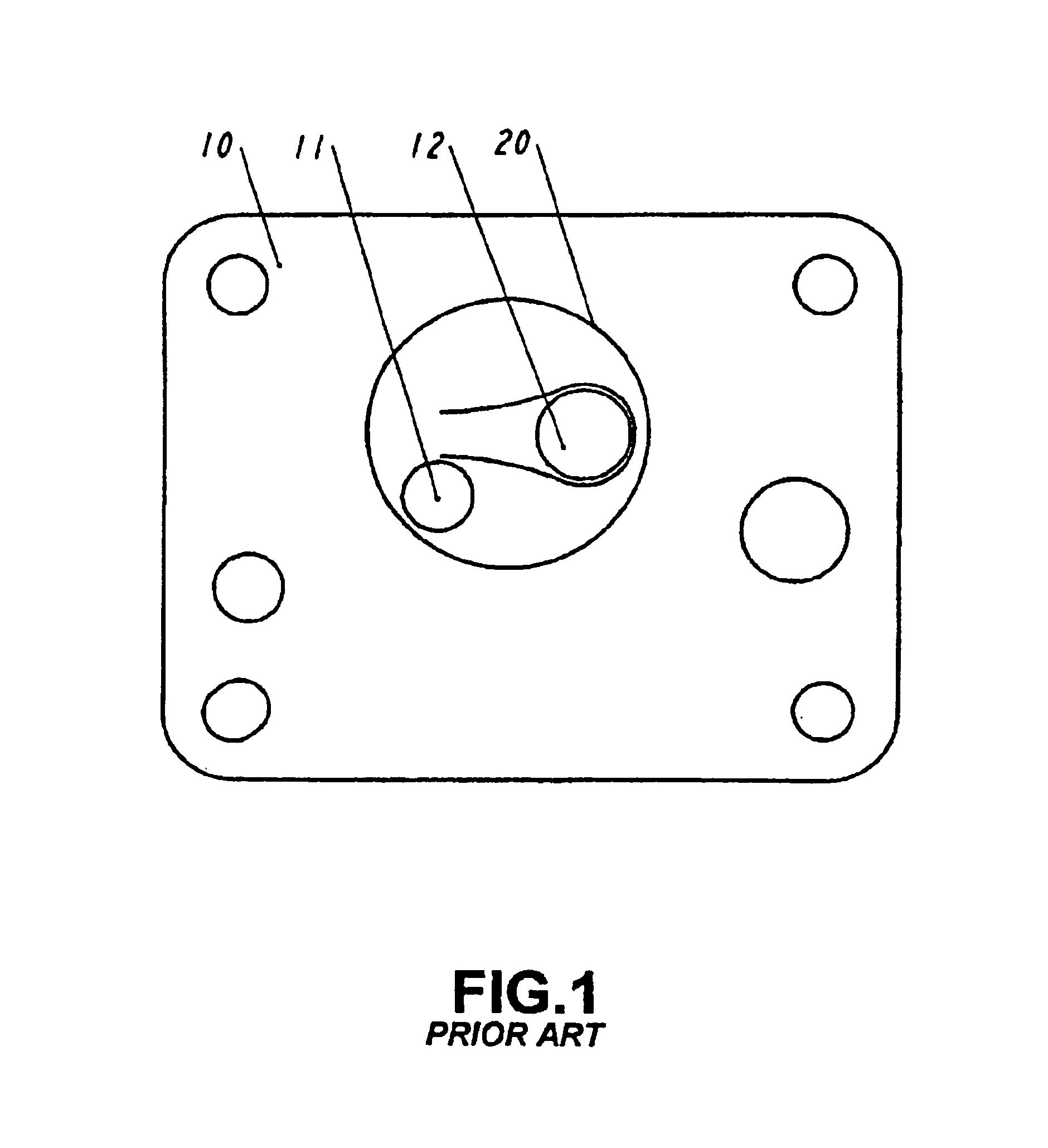
[0018]The present invention will be described in relation to a hermetic compressor of small size comprising, inside a non-illustrated shell, a motor-compressor assembly including a cylinder block defining a compression cylinder 1, inside which is lodged a reciprocating piston, drawing and compressing the refrigerant gas when driven by an electrical motor of the motor-compressor assembly. The compression cylinder 1 has an end closed by a valve plate 10, which is affixed to said cylinder block and provided with a discharge orifice 11 and at least one suction orifice 12, a compression chamber 2 being defined inside the compression cylinder 1, between the piston top and the valve plate 10. The cylinder block further carries a cylinder cover 3, which is affixed to the valve plate 10, so as to insulate the high pressure side from the low pressure side, and which defines, internally, suction and discharge chambers (not illustrated), which are respectively maintained in selective fluid comm...


PUM


Abstract

A suction and discharge valve arrangement for a small hermetic compressor of the type presenting a compression cylinder (1), which has an end closed by a valve plate (10) and which has a suction pipe (5) adjacent to the valve plate (10) and substantially orthogonal to the cylinder axis, the valve plate (10) being provided with a discharge orifice (11) substantially centralized in relation to the axial projection (20) of the internal contour of the compression cylinder (1), and with at least one suction orifice (12), which is internal to said axial projection (20) of the internal contour of the compression cylinder (1), and defining at least part of the extension of a suction passage (P), with an end opened to the inside of the compression cylinder (1) and an opposite end opened and connected to the suction pipe (5) by means of a transition portion (T), which is configured to minimize load losses.

Description

[0001]This application is a continuation of application Ser. No. 10 / 332,206 filed Jan. 3, 2003, now abandoned, which is a National Stage of PCT / BR01 / 00084, filed Jul. 2, 2001, which claims priority to Brazil PI0003292-1, filed July. 17, 2000. has been inserted.FIELD OF THE INVENTION[0002]The present invention refers to a suction and discharge valve arrangement for a hermetic compressor of the type used in small refrigerating appliances, such as refrigerators, freezers, water fountains, etc.BACKGROUND OF THE INVENTION[0003]The energetic efficiency of the small hermetic compressors of refrigeration is greatly attributed to the good performance of its valves in the control of the gas flow.[0004]Refrigeration compressors for domestic use employ one-way valves that control the gas flow during operation. A suction valve controls the gas flow, which comes from the suction line connected to the low pressure side of the refrigeration system, and which is drawn through the compression cylinde...

Claims


Application Information

Patent Timeline
IPC IPC(8): F04B39/10F04B17/00F16K15/00F04B39/00
CPCF04B39/0055F04B39/0061F04B39/1073F04B39/1066Y10S417/902Y10T137/7838
Inventor POSSAMAI, FABRICIO C.LILIE, DIETMAR E.
Owner EMBRACO IND DE COMPRESSORES E SOLUCOES EM REFRIGERACAO LTDA
Why Eureka
Try Eureka