MFLP-valve for a pressure source

a technology of pressure source and valve, which is applied in the direction of check valve, mechanical apparatus, functional valve type, etc., can solve the problems of limiting the overall performance of the system, requiring more than desired design complexity of known pressure control mechanisms, and adding cost to the system of solenoid valves

Active Publication Date: 2019-12-03
MEDELA HLDG AG
View PDF8 Cites 0 Cited by
  • Summary
  • Abstract
  • Description
  • Claims
  • Application Information

AI Technical Summary

Benefits of technology

[0010]One example of why the desired base pressure might differ from atmospheric pressure is to minimize repetitive friction on a nipple as it is received in a nipple tunnel of a breastshield during repeated cycles of a vacuum source. For example, it has been observed that when an infant is properly latched onto a mother's breast during feeding, the nipple is held in a substantially constant depth in the infant's mouth relative to the junction of the hard and soft palette. In an effort to mimic this natural action, it may be desirable to hold at least a minimum vacuum that is less than atmospheric pressure, during successive cycles of the vacuum.
[0013]In another embodiment, a sensor may be capable of sensing more than whether the flag is engaged or disengaged with the sensor and can provide more detailed information about the location of the movable pressure system member. For example, different and specific stripes on a flag, where each specific stripe corresponds with a certain position of the movable pressure system member, may be sensed by a sensor and used to provide specific information about the location of the movable pressure system member. By using this or similar techniques, the speed at which the pressure system member is moving can also be determined if desired.
[0026]A MFLP-valve of the present disclosure may include an operable cover connectable to a pressure chamber within a medical pressure system, configured to cause a pressure condition in the system upon movement of a movable pressure system member, and operably connected to a flag; and the flag may be configured to indicate a position of the movable pressure system member in the pressure system. The operable cover may be connectable to the pressure chamber within the pressure system to minimize a pressure differential between the pressure chamber and a volume outside of the pressure chamber.
[0037]A system for extracting milk from a lactating human mother according to the present disclosure may include a breastpump, a pressure generating device including at least one of a piston and a diaphragm that generates pressure in the system, and a MFLP-valve that physically opens when the pressure generating device arrives at a return position at an end of a stroke of the pressure generating device. The pressure generating device physically opens the valve at the end of the stroke to connect the pressure in the system with external pressure, allowing the pressure in the system to equalize with external pressure or reducing a pressure differential between the system and external pressure.

Problems solved by technology

The known pressure control mechanisms may require more than desired design complexity.
For example, the piston-cylinder / aperture design may limit the overall performance of the system.
The solenoid valve also adds cost to the system, and may generate undesirable noise in the system.
For these and other reasons, previously-designed pressure control systems may introduce limitations for optimizing the design.

Method used


Image

  • MFLP-valve for a pressure source
  • MFLP-valve for a pressure source
  • MFLP-valve for a pressure source

Examples


Embodiment Construction

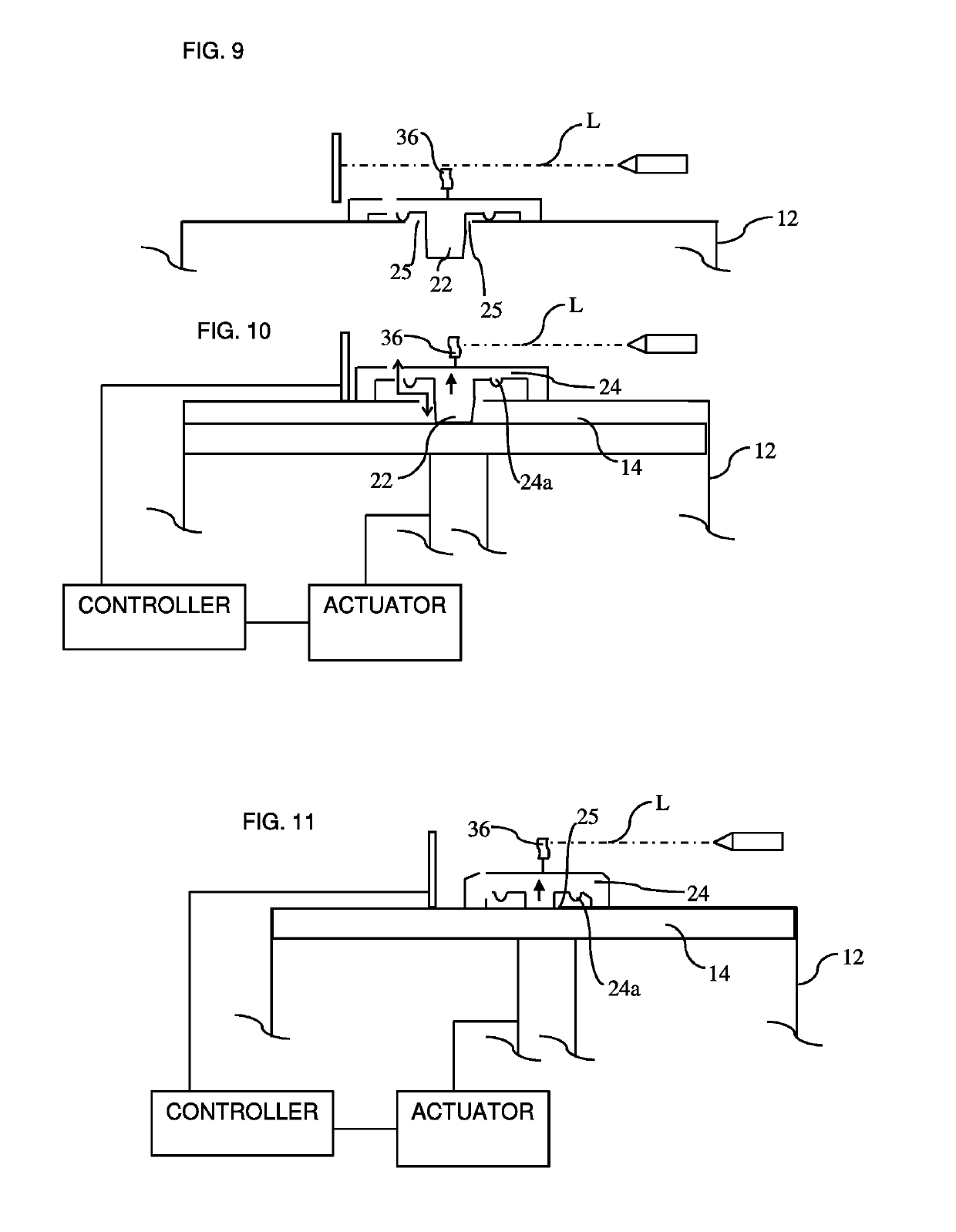
[0060]In accordance with the principles of the present disclosure, a pressure source, such as a pressure source 10 of a breastmilk expression device, for example, includes a pressure generating chamber 12 having a movable pressure system member 14 therein. The movable pressure system member may be actuated by an actuator 16, as illustrated in FIG. 1. A MFLP-valve 18 is associated with an end wall of the pressure generating chamber 12. As used herein, the term “MFLP-valve” refers to a pressure modification valve that can be configured to be coupled with a sensor flag, either directly or indirectly. The MFLP-valve 18 can be secured in a sealed relationship with an aperture 25 in a wall of the pressure generating chamber 12, or can otherwise be positioned as desired on or near the pressure generating chamber 12 or connected to a connector or tubing extending from the pressure generating chamber 12. In an embodiment, the MFLP-valve 18 can be displaced from a sealed condition to an unsea...


PUM


Abstract

A mechanical fluid pressure modification valve, or “MFLP-valve”, is set forth. The MFLP-valve can be actuated upon movement of a movable pressure system member of a medical pressure system reaching a selected position. Additionally, the MFLP-valve can be actuated based on a pressure condition of the system. When the MFLP-valve unseals, a pressure differential between a pressure chamber and a volume outside of the chamber can be relieved. Disengagement of the movable pressure system member from the MFLP-valve can enable the MFLP-valve to re-seal. The MFLP-valve may include a flag that indicates the position of the movable pressure system member. The MFLP-valve may be provided in a diaphragm-type pressure source.

Description

CROSS-REFERENCE TO RELATED APPLICATION[0001]This application claims priority to U.S. Provisional Patent Application No. 62 / 205,419 filed Aug. 14, 2015 entitled “MFLP-Valve for a Pressure Source,” the entire disclosure of which is hereby expressly incorporated by reference herein.FIELD OF THE DISCLOSURE[0002]The present disclosure relates generally to pressure systems, such as breastmilk expression systems, including breastpumps, and, more particularly, to a mechanical fluid pressure modification valve (hereinafter MFLP-valve) that provides relief and / or intake for fluid in a pressure system, and that may be used in combination with a flag selectively detected by a sensor.BACKGROUND[0003]Pressure systems, such as breastmilk expression systems, have been disclosed that include mechanisms to selectively modify pressure within the system. For instance, U.S. Pat. No. 5,007,899 discloses a breastpump with a piston pump having an aperture in a piston cylinder. The breastpump exposes the va...

Claims


Application Information

Patent Timeline
Patent Type & Authority Patents(United States)
IPC IPC(8): A61M1/06A61M39/22A61M39/24
CPCA61M1/062A61M39/227A61M1/06A61M2205/3337A61M2205/3331A61M2039/2486A61M2205/332F16K15/18A61M1/742A61M1/81A61M1/06935
Inventor GIST, JAHICHO, DAVIDRIGERT, MARIO
Owner MEDELA HLDG AG
Why Eureka
Try Eureka