
Portable radio terminal unit

a portable radio and terminal technology, applied in the direction of substation equipment, coupling contact members, wireless communication, etc., can solve the problems of significant antenna characteristics, and achieve the effect of reducing deterioration of antenna characteristics, facilitating connection of antenna with radio circuit board or assembling antenna into the uni

Inactive Publication Date: 2006-07-25
NEC CORP
View PDF37 Cites 188 Cited by
  • Summary
  • Abstract
  • Description
  • Claims
  • Application Information

AI Technical Summary

Benefits of technology

[0007]It is therefore an object of the present invention to provide a portable radio terminal unit which reduces deterioration of the antenna characterisitics by user's body to maintain satable communication characteristics when the antenna is made compact and built in a unit body.
[0008]Another object of the present invention is to provide a portable radio terminal unit which facilitates connection between an antenna and a circuit board and assembling when the antenna is down-sized and built in a unit body.
[0015]By this, the built-in antenna may not contact with the user's body and may not be covered by the user's body to reduce deterioration of antenna characteristics. Also, connection of the antenna with the radio circuit board or assembling of the antenna into the unit can be facilitated.

Problems solved by technology

In such case, it is likely that the user may contact with a portion near the antenna by hand or user's head or users ear may be in close proximity of the antenna to significantly deteriorate antenna characteristics.
On the other hand, even if the antenna is arranged on a lower portion of the casing (microphone side) of terminal unit, when the antenna is mounted on the rear casing side opposite to the front casing where the operation panel is provided, the portion near the antenna can be covered by the hand of the user to be a cause of deterioration of the antenna characteristics.

Method used


Image

  • Portable radio terminal unit
  • Portable radio terminal unit
  • Portable radio terminal unit

Examples


Embodiment Construction

[0030]The present invention will be discussed hereinafter in detail in terms of the preferred embodiment of a portable ratio terminal unit according to the present invention with reference to the accompanying drawings. In the following description, numerous specific details are set forth in order to provide a thorough understanding of the present invention. It will be obvious, however, to those skilled in the art that the present invention may be practiced without these specific details.

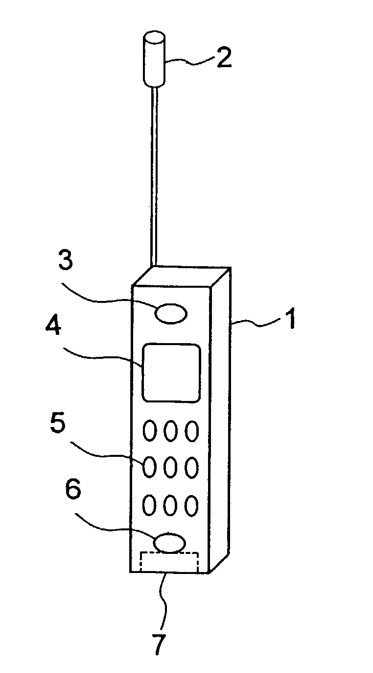
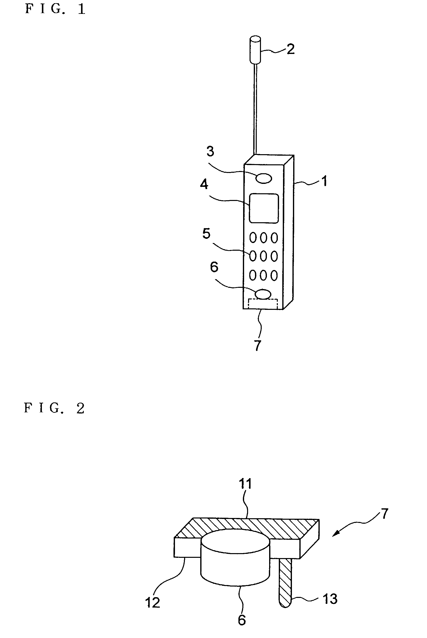
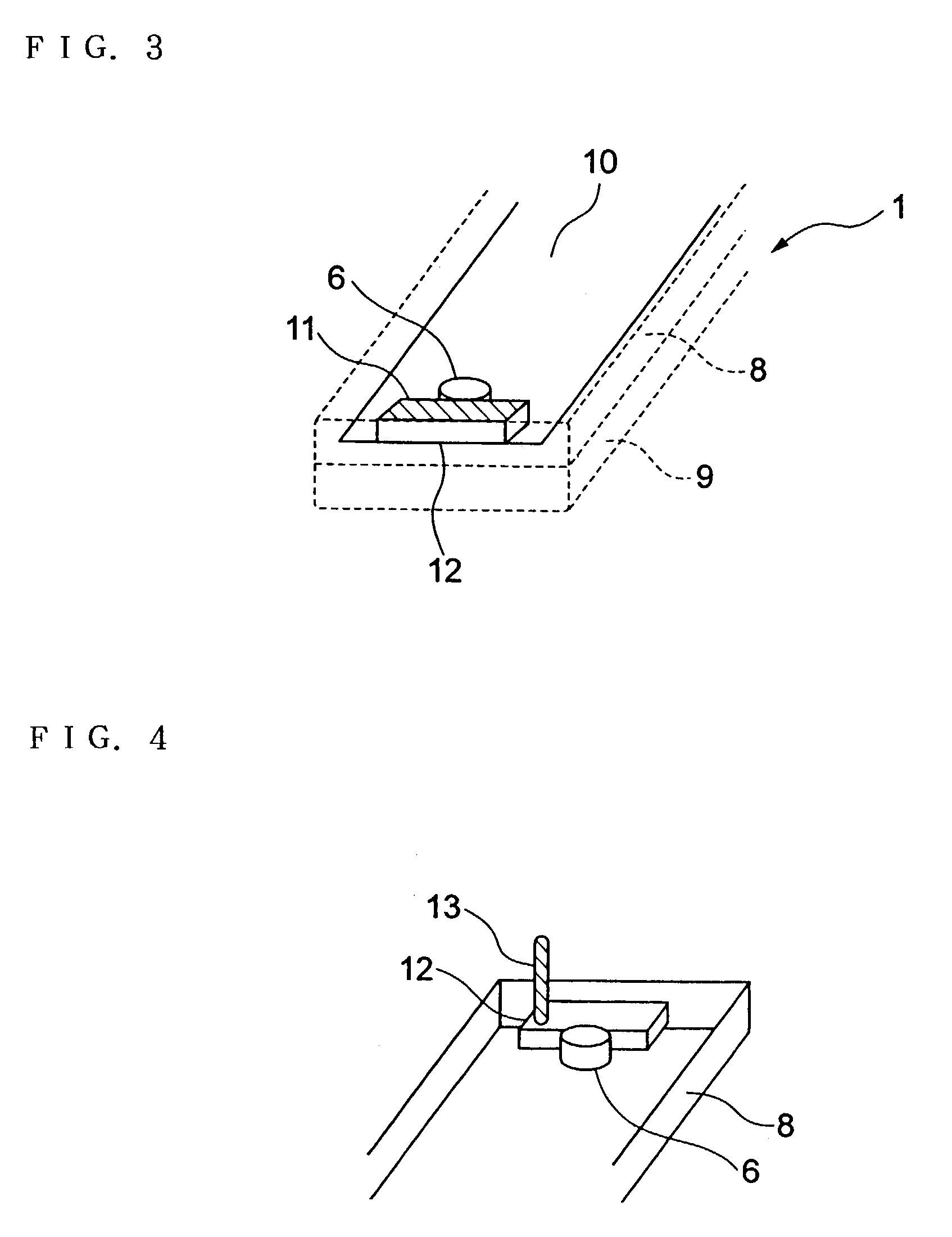
[0031]FIG. 1 is an illustration showing a mounting position of a built-in antenna in the preferred embodiment of a portable radio terminal unit according to the present invention. Referring to FIG. 1, an external antenna 2, a receiver 3, a display portion 4, operation keys 5 and a microphone unit 6 are mounted in a casing 1. Furthermore,in the casing 1, a compact built-in antenna 7 is also mounted. The built-in antenna 7 is provided below the microphone unit 6 in contact with the microphone unit.

[003...


PUM


Abstract

In a portable radio terminal unit, when a built-in antenna is provided, influence of user's body is to be reduced as small as possible to prevent deterioration of antenna characteristics. The built-in antenna is arranged in contact with a microphone unit positioned at lower portion of a unit casing. The microphone unit is mounted on a front casing forming the casing. Therefore, the built-in antenna is also mounted on the front casing. Thus, even during calling and browsing display, the built-in antenna may not contact with a user's head or may not be covered by the user's hand to reduce deterioration of the antenna characteristics for maintaining more stable communication characteristics.

Description

BACKGROUND OF THE INVENTION[0001]1. Field of the Invention[0002]The present invention relates generally to a portable radio terminal unit. More particularly, the invention relates to a compact portable radio terminal unit, such as a cellular telephone unit housing an antenna within a unit casing.[0003]2. Description of the Related Art[0004]Associating with evolution of mobile communication in the recent years, technical advancement and down-sizing of portable radio terminal are quickly progressed. In general, upon calling using the cellular telephone unit as the portable radio terminal, unless using earphone microphone or the like, user inherently use the unit holding in hand and placing the unit in the vicinity of a head. On the other hand, in case of key operation upon transmitting electronic mail message or the like or in case of watching a screen, the user uses the unit with holding in hand.[0005]When the antenna is built-in a main body portion of the terminal unit for down-sizi...

Claims


Application Information

Patent Timeline
IPC IPC(8): H04B1/38H04M1/00H01R13/11H01Q1/24H01Q1/38H04B1/3822H04B7/26H04M1/02H04W16/28H04W88/02
CPCH01Q1/38H01Q1/243H04B1/3838
Inventor HARANO, NOBUYA
Owner NEC CORP
Learn More