
Posterior chamber lens implant

a lens implant and anterior chamber technology, applied in the field of posterior chamber lens implants, can solve the problems of poor glare resistance of lenses, only restoring far vision for patients, and posterior chamber lens implants not restoring the type of near vision needed

Inactive Publication Date: 2006-07-25
CUKROWSKI WALTER
View PDF11 Cites 24 Cited by
  • Summary
  • Abstract
  • Description
  • Claims
  • Application Information

AI Technical Summary

Benefits of technology

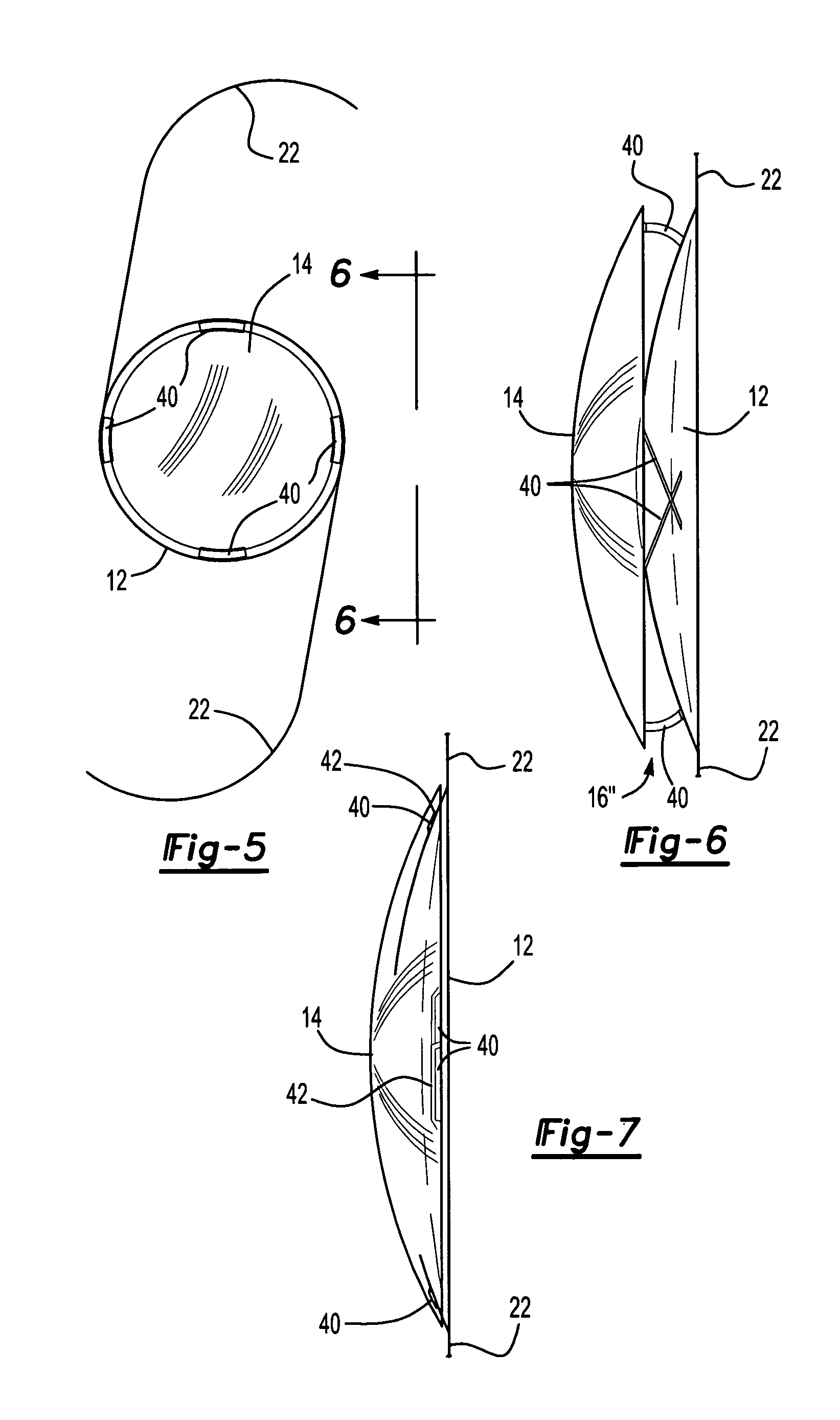
"The present invention provides a multi-focal posterior chamber lens implant that overcomes the disadvantages of previous implants. The implant has two lenses with different refractive powers, one in the range of 15-25 diopters and the other in the range of 0.1-10 diopters. The lenses are secured together in a spaced apart relationship, with the first lens positioned posteriorly of the second lens. The lenses can be made of flexible materials, but once implanted, they retain their shape and spacing relative to each other. The combination of the two lenses provides both near and far vision for the patient."

Problems solved by technology

A primary disadvantage of many of these previously known posterior chamber lens implants, however, is that such lens implants are only capable of restoring far vision for the patient, especially when the patient is of middle age or older.
For such patients, the previously known posterior chamber lens implants do not restore near vision of the type necessary for reading.
A primary disadvantage, however, of these previously known multi-focal lenses is that such lenses are particularly susceptible to glare, particularly at night.
Consequently, such multi-focal lenses have not achieved widespread use or acceptance.

Method used


Image

  • Posterior chamber lens implant
  • Posterior chamber lens implant
  • Posterior chamber lens implant

Examples


Embodiment Construction

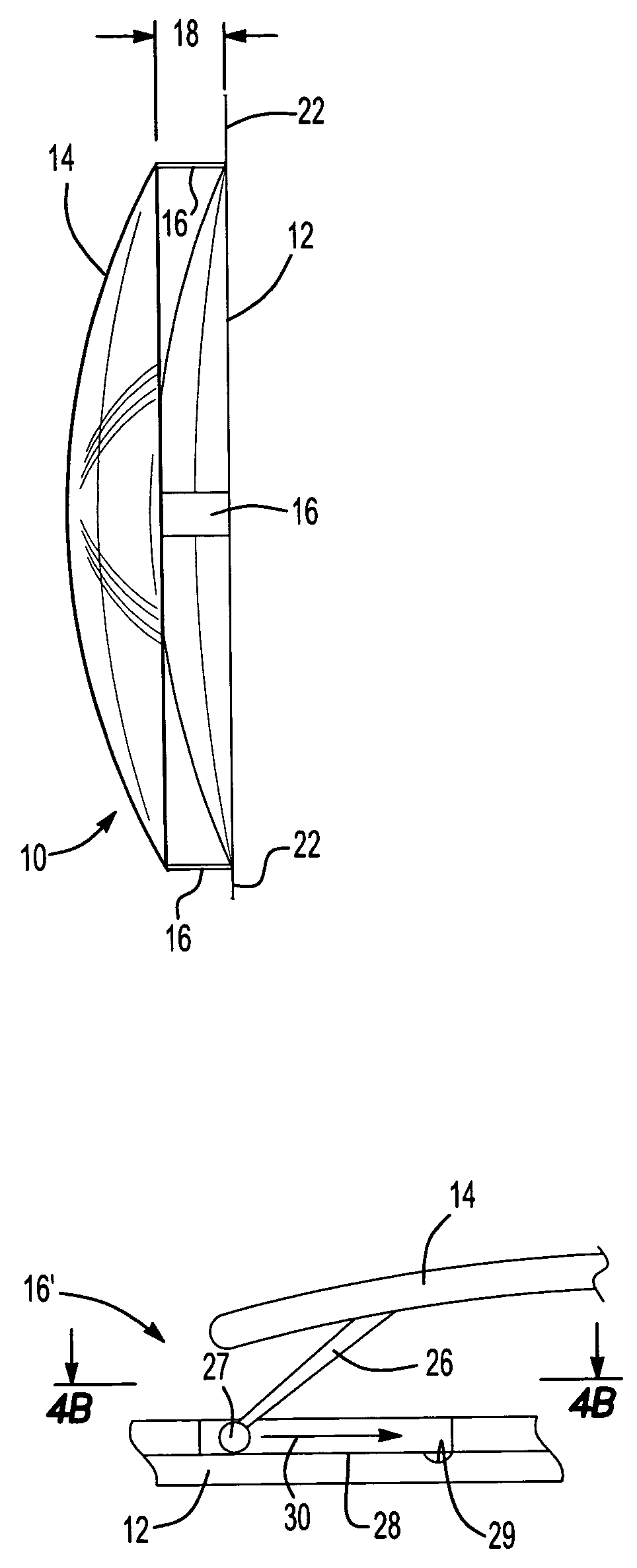
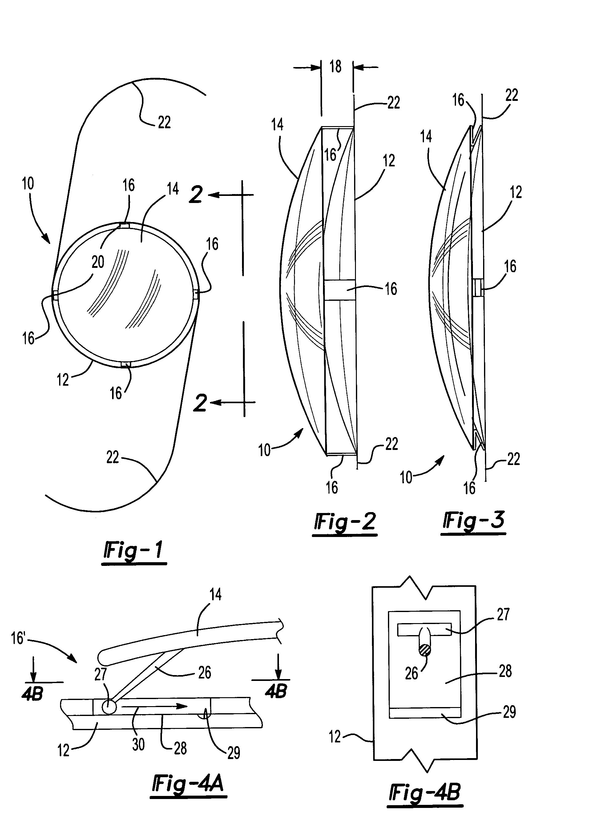
[0025]With reference first to FIGS. 1 and 2, a first preferred embodiment of the posterior chamber lens implant 10 of the present invention is shown and comprises a first lens 12 and a second lens 14. Both lenses 12 and 14 are generally circular in shape as best shown in FIG. 1, with the second lens 14 having either the same or a somewhat smaller diameter than the first lens 12.

[0026]The first lens has a refractive power that is greater than the refractive power of the second lens 14. Preferably, the first lens 12 has a refractive power in the range of 15–25 diopters while the second lens 14 has a refractive power in the range of 0.1–10 diopters.

[0027]The lenses 12 and 14 may be constructed of any conventional material such a silicone, acrylic, PMMA and the like. Furthermore, even though the lenses 12 and 14 may be constructed of a flexible material to facilitate their insertion into the posterior chamber during surgery, once the lens implant 10 is positioned within the posterior ch...


PUM


Abstract

A posterior chamber lens implant for use after extracapsular surgery. The lens implant includes a first lens having a predetermined refractive power and a second lens having a second predetermined refractive power. A support structure maintains the first and second lenses in a spaced apart relationship relative to each other. The lens implant achieves both near and far vision.

Description

BACKGROUND OF THE INVENTION[0001]I. Field of the Invention[0002]The present invention relates to a posterior chamber implant for use after extracapsular surgery.[0003]II. Description of Related Art[0004]In extracapsular surgery, a surgical opening is formed through the front membrane of the lens of the human eye and the cataracts and the fluids within the interior of the lens are then surgically removed. During such surgery, the posterior capsule of the lens is usually left intact so that it forms a barrier between the vitreous humor and the aqueous humor in the eye.[0005]After removal of the cataracts and other material within the original lens, it is necessary to replace the eye lens with an artificial lens implant in order to restore sight to the eye. Although such artificial lenses have in the past been placed in the anterior chamber, it has been found that placement of the artificial lens in the posterior chamber, i.e. in the lens sack, is superior for many reasons.[0006]These ...

Claims


Application Information

Patent Timeline
Patent Type & Authority Patents(United States)
IPC IPC(8): A61F2/16
CPCA61F2/1613A61F2/1648A61F2250/0053
Inventor CUKROWSKI, WALTER
Owner CUKROWSKI WALTER
Learn More