Eureka AIR delivers breakthrough ideas for toughest innovation challenges, trusted by R&D personnel around the world.

Iron-type golf club head

a golf club head and iron-type technology, applied in the field of golf club heads, can solve the problems of increasing production costs, little can be done to tune the weight distribution of the club head,

Inactive Publication Date: 2006-07-18
TAYLOR MADE GOLF
View PDF28 Cites 36 Cited by
  • Summary
  • Abstract
  • Description
  • Claims
  • Application Information

AI Technical Summary

Benefits of technology

[0006]The internal chamber, or a plurality of internal chambers defined by the annular mass, can be filled with a polymer, foam or high density filler, for example, to further manage the weight distribution of the club head. If the internal chamber or chambers within the top portion of the annular mass are left unfilled, lowering of the center of gravity (CG) of the head is maximized. A low CG is preferred by many golfers for the added ease in launching a golf ball. If the heel portion of a plurality of internal chambers in the top portion are filled, then the CG is moved toward the heel. This low, heelward CG location is preferred by many players for the ease of launch and ease of promoting right to left ball flight (slice reduction). Alternatively, internal chambers 44 disposed at the extreme ends of the heel and toe can be filled to achieve increased heel and toe weighting. Thus, the club head can be tuned to accommodate requirements of an individual golfer.

Problems solved by technology

Most club heads have a fixed weight distribution; consequently, very little can be done to tune the weight distribution of a club head to the particular needs of an individual golfer.
To accommodate golfers across all skill levels, golf club manufacturers typically must carry several distinct product lines of golf clubs, which can increase production costs.

Method used


Image

  • Iron-type golf club head
  • Iron-type golf club head
  • Iron-type golf club head

Examples


Embodiment Construction

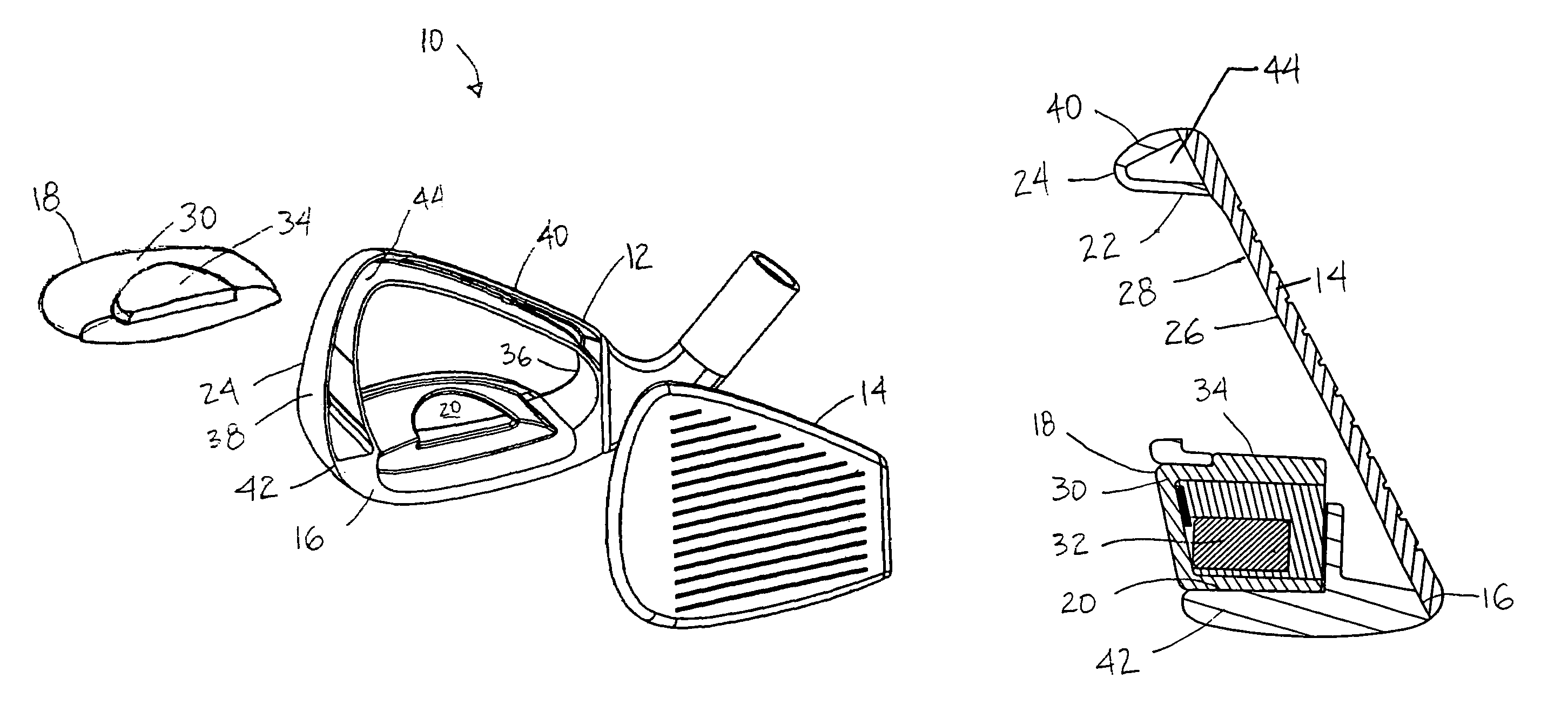
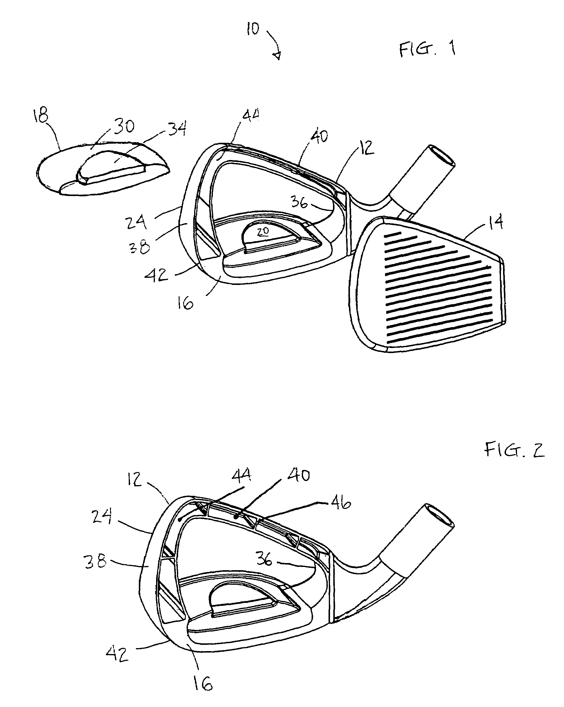
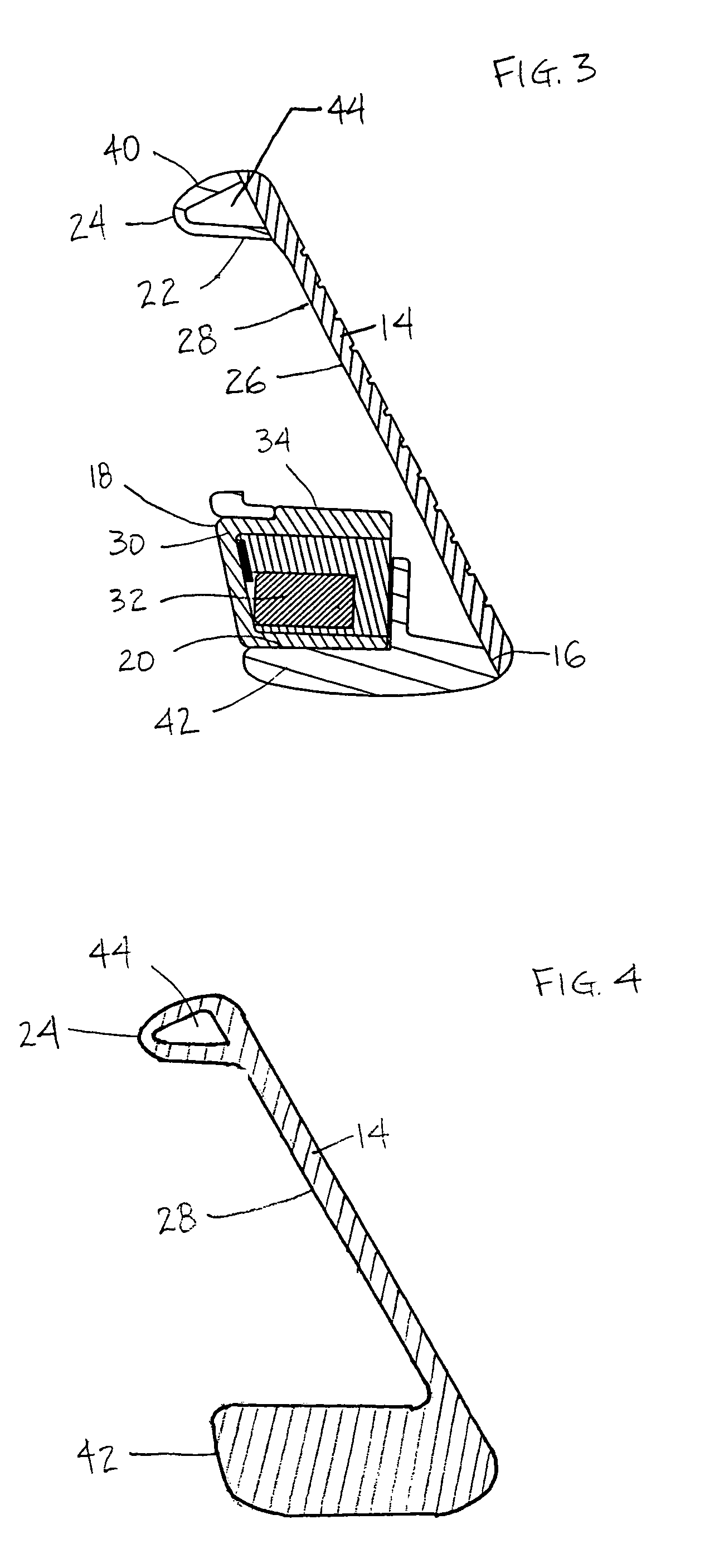
[0018]In accordance with the present invention, a perimeter weighted iron-type golf club head 10 includes a face plate 14 having a front side defining a striking face of the club head and a body 12 having an annular mass 24 disposed behind the striking face. The annular mass 24 extends about a periphery of the face plate 14, thereby defining an external cavity 28 centrally located on a rear surface 26 of the face plate. The annular mass 24 includes a top portion 40 extending along a top edge of the face plate 14, a toe portion 38 extending along a toe edge of the face plate, a heel portion 36, and a bottom portion 42. One or more internal chambers 44 are provided in at least a part of the top portion 40 of the annular mass 24.

[0019]With reference to the illustrative drawings, and particularly to FIG. 1, there is shown a club head 10 having a body 12 and a separately formed face plate 14. The face plate 14 is preferably welded about its periphery to a front 16 of the body 12. A weigh...


PUM


Abstract

The present invention resides in a perimeter-weighted, iron-type golf club head incorporating one or more internal chambers. The golf club head has a face plate defining a striking face of the club head and a body having an annular mass disposed behind the striking face. The annular mass extends about a periphery of the face plate defining an external cavity on a rear side of the face plate. The annular mass includes a top portion extending along a top edge of the face plate, a toe portion extending along a toe edge of the face plate, a heel portion, and a bottom portion. At least one internal chamber is located adjacent to the top edge, as defined by the top portion of annular mass. The club head also includes a weight member disposed in a recess defined by the bottom portion of the annular mass. The internal chamber, or a selected number of a plurality of internal chambers defined by the annular mass, can be filled to further manage the weight distribution of the club head. Thus, the club head can be tuned to accommodate requirements of an individual golfer.

Description

BACKGROUND OF THE INVENTION[0001]The present invention relates generally to golf club heads and, more particularly, to iron-type golf club heads.[0002]The weight distribution of a club head is an important design consideration. Many iron-type golf club heads are configured in what is commonly known as “cavity back” design. Such designs allocate weight about the club's periphery. This peripheral weighting is generally considered to provide greater forgiveness for off-center shots than traditional blade-style club heads. As such, cavity back designs often are preferred by high handicap golfers.[0003]Another, sometimes competing, consideration relates to the location of the club head's center of gravity (CG). A club having a low CG location is often preferred typically by less skilled players, for the increased ease in launching a golf ball. Alternatively, in the hands of an experienced golfer, a club head having a more centrally located CG provides greater control over the flight of t...

Claims


Application Information

Patent Timeline
Patent Type & Authority Patents(United States)
IPC IPC(8): A63B53/04A63B53/06
CPCA63B53/047A63B2053/0491A63B2053/0437A63B2053/0433A63B2053/0416A63B60/02A63B53/0416A63B53/0433A63B53/0437
Inventor WAHL, BRETINES, MARNI
Owner TAYLOR MADE GOLF
Why Eureka
Eureka Blog
Learn More